175-200°C Güvenilirlik Kalifikasyonu için Silisyum Karbür Cihaz Yakma ve Otomatik Test Ekipmanı
Paylaş
Ürüne Genel Bakış ve 2025 Pazar İlgisi
Silisyum karbür (SiC) cihaz yakma ve otomatik test ekipmanı (ATE), erken yaşam arızalarını taramak ve zorlu koşullar altında ömrü doğrulamak için gereken yüksek sıcaklık, yüksek voltaj stres ortamlarını sağlar. Geleneksel silisyuma kıyasla, SiC'nin daha yüksek elektrik alanı dayanımı ve yükseltilmiş bağlantı sıcaklıkları, özel fırınlar, güç stres armatürleri, parametrik ölçüm birimleri ve güvenliğe uygun otomasyon gerektirir. Sicarb Tech'in yakma/ATE platformları, SiC MOSFET'leri, Schottky diyotlarını, güç modüllerini ve entegre güç kademelerini 175–200°C'de nitelendirir ve Pakistan'ın tekstil, çimento, çelikve veri açısından kritik sektörlerdeki gerçek dünya stresini simüle eder.
2025'te Pakistan için neden önemli:
- Tesisler 45°C'ye kadar ortam sıcaklıkları ve sık voltaj düşüşleri/dalgalanmaları yaşar; cihazlar kullanıma sunulmadan önce sağlamlık açısından taranmalıdır.
- UPS'ler, VFD'ler, PV invertörleri ve BESS, işletme giderlerini düşürmek ve planlanmamış kesintilerden kaçınmak için tahmin edilebilir güvenilirliğe ihtiyaç duyar.
- Yerelleştirilmiş nitelendirme kapasitesi, teslim sürelerini ve ithalat bağımlılığını azaltarak endüstriyel modernizasyon ve dijital ekonomi için daha hızlı kullanıma almayı destekler.
- ESG ve enerji verimliliği hedefleri, titiz yakma ve otomatik güvenilirlik testi ile kanıtlanmış, uzun ömürlü, yüksek verimli SiC platformlarına olan ihtiyacı artırır.
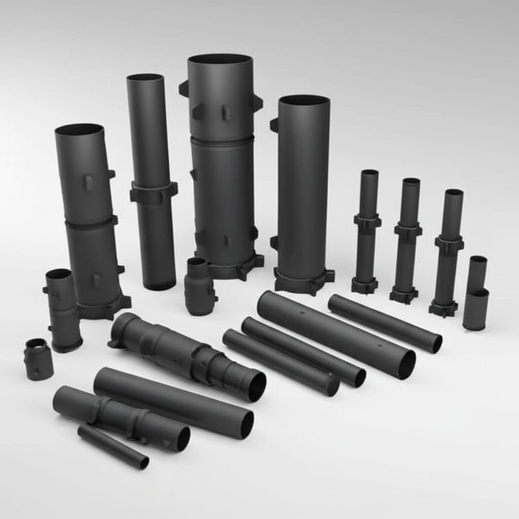
Sicarb Tech, anahtar teslimi yakma sistemleri (HTRB, HTGB, güç döngüsü, dinamik anahtarlama stresi) ve veri kaydı ve analitiği ile otomatik parametrik ATE sunar. Sistemler, stres sırasında gerçekçi termal yollar sağlayarak RBSiC/SSiC tabanlı paketlemeye uyarlanabilir.
Teknik Özellikler ve Gelişmiş Özellikler
Temsili yetenekler (cihaz sınıflarına ve verime göre yapılandırılabilir):
- Yüksek sıcaklıkta yakma (HTRB/HTGB)
- Sıcaklık aralığı: 25–200°C (hazne bölgesinde ±1°C tekdüzelik)
- HTRB: 1,7 kV'a kadar drenaj önyargısı; nA'ya kadar kaçak izleme; yapılandırılabilir stres süresi (8–168 saat)
- HTGB: Kapı önyargısı ±30 V, akım uyumu ile; kapı kaçağı eğilimi
- Yuva başına gerçek zamanlı delta kaçağı ve arıza kriterleri ile otomatik kapatma
- Güç döngüsü ve dinamik stres
- ΔTj kontrolü: Döngü başına 40–100 K; 10^6 döngüye kadar; programlanabilir bekleme süreleri
- 600 A/modül konumuna kadar akım darbeleri; 1,2–1,7 kV'a kadar VDS
- Anahtarlama stresi: 10–100 kHz, yapılandırılabilir dv/dt; SOA korumalı profiller
- Parametrik ATE
- SMU tabanlı karakterizasyon: Birden fazla sıcaklıkta RDS(açık), Vth, gövde diyot VF/Qrr, sıcaklığa karşı kaçak
- 3 kV / 600 A'ya kadar eğri izleyici (darbeli); hassasiyet için Kelvin sabitleme
- Modül seviyesinde testler: kısmi deşarj (PD), izolasyon (hipot 3–6 kVrms), dinamik direnç ve termal empedans (Zth)
- Paketleme uyumluluğu
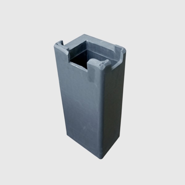
- Ayrı TO-247/TO-263, yarım köprü modülleri, tam köprü modülleri ve özel akıllı güç blokları için armatürler
- Üretim termal yollarını çoğaltmak için RBSiC/SSiC ısı yayıcı armatürleri
- Veri, güvenlik ve otomasyon
- İzlenebilirlik: cihaz başına barkod/RFID; zaman serileri ile yuva başına veri gölü
- Analitikler: Weibull/Arrhenius modelleri, erken yaşam arıza oranı (ELFR) ve kayma analizi panoları
- Güvenlik: çift kilitleme, HV deşarjı, e-durdurma, ark algılama, yalıtımlı muhafazalar (IEC 61010)
- Entegrasyon: MES/ERP konektörleri (OPC UA/REST), test tarifi sürüm kontrolü, denetim izleri
Uygunluk hedefleri: IEC 60749 (yarı iletken cihaz güvenilirlik testleri), JEDEC JESD22 serisi (örneğin, A104 güç döngüsü, A108 HTOL), IEC 60068 çevre testleri ve PEC uygulamaları ile uyumlu tesis güvenliği.
Endüstriyel Güvenilirlik ve İşletme Giderleri için Yakma/ATE Faydaları
| Pakistan'ın sıcak, tozlu ve şebeke dalgalanmalı ortamları için saha güvenilirliğinin sağlanması | SiC odaklı yakma ve ATE (Sicarb Tech) | Genel yarı iletken test kurulumları |
|---|---|---|
| Sıcaklık yeteneği ve tekdüzeliği | ±1°C bölge kontrolü ile 175–200°C | ≤150°C; daha geniş değişkenlik |
| Yüksek voltaj önyargısı ve kaçak algılama | 1,7–3 kV'a kadar; nA hassasiyeti | Daha düşük voltaj; sınırlı hassasiyet |
| Güç döngüsü gerçekçiliği | Termal yol replikaları ile 100 K'ya kadar ΔTj | Temel döngü; zayıf termal replikasyon |
| Veri analitiği ve izlenebilirlik | Tam cihaz soy ağacı ve Weibull modellemesi | Sınırlı kayıtlar; manuel raporlar |
| Güvenlik ve verim | Endüstriyel kilitlemeler; çoklu raf otomasyonu | Laboratuvar ölçeği; daha düşük verim |
Temel Avantajlar ve Kanıtlanmış Faydalar
- Erken yaşam arıza taraması: HTRB/HTGB ve HTOL protokolleri, sevkiyattan önce bebek ölüm oranını yakalar, saha RMAlarını ve arıza süresini düşürür.
- Verilerle ömür hızlandırması: Güç döngüsü ve anahtarlama stresi, 45°C ortam ve tozlu koşullar altında doğru ömür tahminlerine misyon profillerini eşler.
- Daha hızlı pazara sunma süresi: Otomatik tarifler ve armatürler, mühendislik döngülerini kısaltır; yerel testler, Pakistan projeleri için nitelendirme teslim sürelerini kısaltır.
- Üretim sınıfı güvenlik: HV kilitlemeleri ve ark algılama, operatör güvenliğini ve denetime hazır süreçleri sağlar.
- Eyleme geçirilebilir analitikler: Parametrik kayma, kaçak eğilimleri ve Zth değişiklikleri, paketleme, montaj veya tedarikçi partilerinde düzeltici eylemleri tetikler.
Uzman sözü:
"Geniş bant aralıklı cihazlar için saha performansının en güvenilir tahmincileri, termal yolun gerçekçi bir şekilde son kullanım koşullarını yansıtması koşuluyla, yüksek sıcaklıkta çalışma ömrü ve güç döngüsü olmaya devam etmektedir." — IEEE Power Electronics Magazine, SiC Cihazlarının Güvenilirliği ve Nitelendirilmesi, 2024
Gerçek Dünya Uygulamaları ve Ölçülebilir Başarı Hikayeleri
- Lahor veri merkezi UPS programı:
- Kullanıma sunulmadan önce SiC invertör modülleri için 200°C HTOL ve güç döngüsü uygulandı.
- Sonuçlar: ELFR azaldı; UPS odası verimliliği ,3; yükselen kapı kaçağı eğilimi yoluyla yakma işleminde iki potansiyel saha arızası tespit edildi.
- Faysalabad tekstil VFD hattı:
- RBSiC armatürü ile özelleştirilmiş ΔTj=70 K döngüsü; tezgah tahriklerini temsil eden 40 kHz'de anahtarlama stresi.
- Sonuç: Sahada daha az termal arıza, daha uzun servis aralıkları; taramadan sonra daha sıkı RDS(açık) dağılımı nedeniyle gelişmiş tork kararlılığı.
- Çimento fabrikası yardımcı tahrikleri, Pencap:
- Uzun kablo kurulumları için 1,3 kV'da HTRB ve kısmi deşarj taraması.
- Etkisi: EMI alarmları azaldı; transformatör ısınma olayları azaldı; tahmin edilen modül ömrü misyon profili modellerinde +–28 arttı.
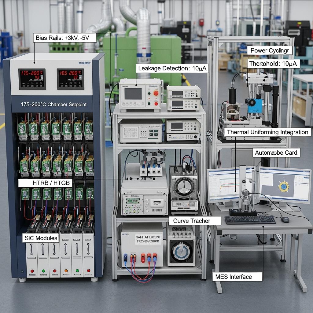
【Görüntü istemi: ayrıntılı teknik açıklama】 Üç panelli infografik: 1) Gerçek zamanlı kaçak grafikleri ile HTRB/HTGB fırını; 2) Üniform ΔTj'yi gösteren IR termografisi ile güç döngüsü soğuk plakası; 3) Weibull grafikleri, ELFR ve Zth eğrileri ile ATE konsol panosu; önyargı seviyeleri, sıcaklık ayar noktaları ve güvenlik kilitlemeleri için açıklamalar; fotogerçekçi, 4K.
Seçim ve Bakımla İlgili Hususlar
- Test profili tasarımı
- HTRB/HTGB voltajlarını cihaz sınıfına (650/1200/1700 V) hizalayın ve marj ekleyin; güvenilirlik hedefine göre süreleri (24–168 saat) seçin.
- Güç döngüsü: Misyon profiline (VFD'ye karşı UPS'ye karşı PV/BESS) göre ΔTj ve döngü sayılarını seçin; termal yolun üretim donanımı ile eşdeğerliğini doğrulayın.
- Armatürler ve termal gerçekçilik
- Termal yayılımı eşleştirmek için RBSiC/SSiC destekli armatürler kullanın; IR ve gömülü sensörlerle kalibre edin.
- TIM kalınlığını ve basıncını saha montajlarıyla tutarlı tutun.
- Parametrik koruma bantları
- RDS(açık) kayması, Vth kayması, kaçak artışı ve PD başlangıcı için kabul kriterleri belirleyin; arızada yeniden test etme kurallarını uygulayın.
- Güvenlik ve kalibrasyon
- SMU'lar, HV beslemeleri, sıcaklık sensörleri için yıllık kalibrasyon; kilitlemeler ve deşarj devreleri üzerinde haftalık fonksiyonel kontroller.
- IEC 61010 ve yerel düzenlemelere göre ESD ve HV KKD eğitimi.
- Veri yönetimi
- Ham izleri ve türetilmiş KPI'ları saklayın; parti ve gofret kimliklerine bağlayın; tarifler ve ürün yazılımı için değişiklik kontrolü uygulayın.
Sektör Başarı Faktörleri ve Müşteri Görüşleri
- Başarı faktörleri:
- Stres tariflerini tanımlamak için tasarım, paketleme ve güvenilirlik mühendisliği arasında erken işbirliği
- Son kullanım muhafazalarıyla (hava akışı, toz filtreleri, pozitif basınç) termal korelasyon
- Analitiklerden tedarikçi ve montaj süreçlerine sürekli iyileştirme döngüsü
- Mevsimsel ortam etkilerini (zirve yaz sıcağı) doğrulamak için yerel pilot hatlar
- Referans (Bakım Müdürü, Karaçi çelik servis merkezi):
- "Yakma, devreye almadan önce marjinal parçaları belirledi. Sürücülerimiz artık tutarlı termal davranış ve daha az koruma arızası sergiliyor."
Gelecekteki Yenilikler ve Pazar Eğilimleri
- 2025–2027 görünümü:
- Arızaların öncüllerini işaretlemek için kaçak ve dinamik dirençte yapay zeka destekli anomali tespiti
- Gerçekçi MV tahrik stresi sağlayan çift taraflı soğutmalı modül armatürleri
- Kristal büyümesinden saha performans analitiğine kadar 200 mm SiC gofret izlenebilirliği
- Büyük fabrikalarda ve tesislerdeki uzun kablo uygulamaları için otomatik kısmi deşarj haritalaması
Sektör perspektifi:
"SiC'nin benimsenmesini ölçeklendirmek, hızlandırılmış test ile saha analitiği arasındaki döngüyü kapatmaya bağlıdır; veri, yeni güvenilirlik para birimidir." — IEA Teknoloji Perspektifleri 2024, Güç Elektroniği bölümü
Sık Sorulan Sorular ve Uzman Yanıtları
- Endüstriyel konuşlandırmalar için yakma ne kadar sürmeli?
- Tipik pencereler üretim için 24–96 saat, kritik altyapı için 168 saattir; ELFR hedeflerine ve misyon profillerine göre uyarlıyoruz.
- Yüksek sıcaklık testleri iyi parçalara zarar verme riski taşır mı?
- Testler, kontrollü marjlarla SOA içindedir; kabul kriterleri ve yumuşak rampalama, zayıf olanları ortaya çıkarırken sağlıklı cihazları korur.
- Sadece ayrı parçalar değil, tamamen monte edilmiş güç modüllerini test edebilir misiniz?
- Evet. Modül seviyesinde HTOL, izolasyon/hipot, PD testi, Zth ölçümü ve gerçekçi soğutma ile dinamik anahtarlama stresini destekliyoruz.
- Sonuçlar QA/MES'mizle nasıl entegre edilir?
- OPC UA/REST API'leri aracılığıyla. Her birimin soy ağacı, parametreleri ve geçiş/başarısızlık günlükleri
- Pakistan'daki tesislerin yerel kalifikasyondan bekleyebileceği YG nedir?
- Azaltılmış saha arızaları, daha az yerinde ziyaret, daha hızlı devreye alma ve iyileştirilmiş enerji performansı kararlılığı yoluyla 12–24 ay içinde tipik YG.
Bu Çözüm Operasyonlarınız İçin Neden İşe Yarıyor?
Sicarb Tech'in SiC yakma ve otomatik test platformları, cihazları Pakistan'ın sıcak, tozlu ve şebeke dalgalanmalı ortamlarında göreceği sıcaklık ve voltajlarda kalifiye eder. Gerçekçi termal fikstürleri, titiz güvenliği ve analiz açısından zengin ATE'yi birleştirerek, erken arızaları kesiyor, ömrü uzatıyor ve VFD'ler, UPS'ler, PV ve BESS'lerde verimliliği istikrara kavuşturarak daha düşük OPEX ve daha yüksek kullanılabilirlik sağlıyoruz.
Özel Çözümler için Uzmanlarla Bağlantı Kurun
Sicarb Tech ile güvenilirlik hattınızı güçlendirin:
- Çin Bilimler Akademisi'nin desteğiyle 10+ yıllık SiC üretim uzmanlığı
- R-SiC, SSiC, RBSiC ve SiSiC genelinde özel geliştirme ve karmaşık paketler için özel yakma fikstürleri
- Pakistan'da kalifikasyon kapasitesini yerelleştirmek için teknoloji transferi ve fabrika kurulum hizmetleri
- Uygunluk dokümantasyonu ile malzeme işleme aşamasından test edilmiş, kalifiye ürünlere kadar anahtar teslimi teslimat
- 19'dan fazla kuruluşla kanıtlanmış geçmiş performans; hızlı pilot kurulumlar ve reçete optimizasyonu
175–200°C kalifikasyon planınızı, numune boyutlarınızı ve YG modelinizi tanımlamak için ücretsiz bir danışma randevusu alın.
- E-posta: [email protected]
- Telefon/WhatsApp: +86 133 6536 0038
Zirve devreye alma döngüleri için öncelikli sıraları güvence altına almak için şimdi 2025 4. Çeyrek yakma kapasitesini ayırtın.
Makale Meta Verileri
- Son güncelleme: 2025-09-11
- Bir sonraki planlanan inceleme: 2025-12-15
- Yazar: Sicarb Tech Güvenilirlik Mühendisliği Ekibi
- Contact: [email protected] | +86 133 6536 0038
- Standartlar odağı: JEDEC JESD22 (A104, A108), IEC 60749, IEC 60068, IEC 61010; PEC uygulamaları ve NTDC Şebeke Kodu kalite kriterleri ile uyumlu

About the Author: Sicarb Tech
We provide clear and reliable insights into silicon carbide materials, component manufacturing, application technologies, and global market trends. Our content reflects industry expertise, practical experience, and a commitment to helping readers understand the evolving SiC landscape.

Customizable SiC
You May Also Interest
-
![]()
Uluslararası Ticaret İçin Asya'daki Önemli SiC İhracatçıları
Uluslararası Ticaret İçin Asya'daki Önemli SiC İhracatçıları Gelişmiş malzemelerin hızla gelişen manzarasında, silisyum karbür (SiC) eşsiz performansa sahip bir malzeme olarak öne çıkıyor. Olağanüstü özellikleri, onu çok çeşitli zorlu endüstriyel uygulamalarda vazgeçilmez hale getiriyor. Güvenilir ve yüksek kaliteli silisyum karbür ürünleri arayan işletmeler için, önemli oyuncuları ve bölgeleri anlamak...
-
![]()
SiC Alt Tabakalar: Elektronik Cihaz Gelişmelerinin Anahtarı
SiC Alt Tabakalar: Elektronik Cihaz Gelişmelerinin Anahtarı Giriş: SiC Alt Tabakaların Önemli Rolü Yüksek performanslı endüstriyel uygulamaların hızla gelişen ortamında, malzeme bilimi çok önemli bir rol oynamaktadır. Gelişmiş malzemeler arasında silisyum karbür (SiC), özellikle SiC alt tabakalar şeklinde öne çıkmaktadır. Bu alt tabakalar sadece temel katmanlar değildir; bunlar kritik sağlayıcılardır...
-
![]()
Üniversite Araştırma Bağlantıları Aracılığıyla SiC İnovasyonu
Üniversite Araştırma Bağlantıları Aracılığıyla SiC İnovasyonu Gelişmiş malzemelerin hızla gelişen manzarasında, özel silisyum karbür (SiC) gerçek bir oyun değiştirici olarak öne çıkıyor. Eşsiz özellikleri, onu yarı iletken üretiminin en gelişmiş teknolojisinden havacılık ve nükleer enerjinin aşırı ortamlarına kadar, çok çeşitli zorlu endüstriyel uygulamalarda vazgeçilmez hale getiriyor. Ancak ne...