Silicon Carbide Inverter Power Stages for VFDs, Solar Inverters, and Energy Storage Systems
Share
Product Overview and 2025 Market Relevance
Silicon carbide (SiC) inverter power stages are purpose-built assemblies that integrate SiC MOSFET modules, gate drivers, DC-link capacitors, current/voltage sensing, and thermal management to convert DC to AC at high efficiency and high switching frequency. For Pakistan’s textile, cement, steel, and rapidly growing clean energy sectors, these stages unlock compact, low-loss Variable Frequency Drives (VFDs), grid-tied solar inverters, and bidirectional battery energy storage systems (BESS).
Why it matters in 2025:
- Grid variability: Frequent sags, swells, and harmonics stress conventional silicon IGBT inverters. SiC offers higher dv/dt control, faster response, and lower heat under the same conditions.
- High ambient/dust: Industrial rooms reaching 40–45°C and dusty environments (cement, textile) demand robust thermal margins and sealed, compact designs—strengths of SiC.
- Efficiency and OPEX: Electricity tariffs and diesel backup costs are rising. SiC’s 5–8% system efficiency uplift reduces both energy spend and cooling load.
- Space constraints: MCC rooms and UPS/inverter halls are footprint-limited. SiC’s >10 kW/L power density supports denser installations and brownfield retrofits.
- Energy transition: Pakistan’s solar and hybrid microgrids, plus data center and industrial BESS, benefit from high-frequency, bidirectional SiC stages that improve round-trip efficiency and grid compliance.
Sicarb Tech designs and customizes SiC inverter power stages to local operating realities—220/400 V, 50 Hz systems, long motor cable runs, transformer interactions, and compliance with PEC practices and NTDC Grid Code quality expectations.
Technical Specifications and Advanced Features
Representative specifications (customizable per project):
- Voltage classes: 650 V, 1200 V, 1700 V SiC MOSFET modules
- Power ratings: 5 kW to 500 kW per inverter chassis; parallelable for higher power
- Switching frequency: up to 100 kHz (application-optimized 16–60 kHz typical for VFDs; 40–80 kHz for PV/BESS)
- Efficiency: inverter stage peak >98%; weighted EU/CEC >97% (PV); VFD efficiency 97–98% typical
- Junction temperature: Tj,max 175°C (select devices up to 200°C)
- Topologies: 2-level, 3-level NPC/TNPC/ANPC; bidirectional for BESS (buck/boost and inverter modes)
- Gate drive: ±15–18 V, DESAT protection, soft turn-off, Miller clamp, CMTI >100 V/ns
- DC link: low-ESL film capacitors; segmented busbars to minimize loop inductance
- Sensing: Hall or shunt current sensing, precision voltage dividers, temperature/insulation monitoring
- Thermal: air-cooled or liquid-cooled; AlN/Si3N4 DBC; optional SSiC/RBSiC heat spreaders
- Protection: OCP/Ovp/Uvp, short-circuit withstand (tSC), thermal rollback/shutdown, ground fault detection
- Control interface: PWM/FOC-ready; grid synchronization (PLL) for PV/BESS; Modbus/RS485/CAN/Ethernet options
- Compliance targets: IEC 61800 (VFD), IEC 62109 (PV inverters), IEC 62933/IEC 62477-1 (BESS/converters), IEC 61000 EMC; aligned to PEC safety practices and NTDC Grid Code
Sicarb Tech advanced features:
- Laminated DC link to achieve ultra-low stray inductance for clean, low-overshoot switching
- Field-proven gate driver suite with parameterizable dv/dt for legacy motor insulation
- Conformal-coated, dust-resilient builds and positive-pressure enclosure options for cement/textile plants
- Digital diagnostics: SOA margining, lifetime counters for capacitors/fans, cloud-ready telemetry
High-Efficiency Operation in Harsh Conditions
| High-density inverter stage performance for Pakistan’s industries | SiC inverter power stage | Silicon IGBT inverter stage |
|---|---|---|
| Peak/weighted efficiency | >98% / >97% | 94–96% / 92–94% |
| Switching frequency capability | Up to 100 kHz | 10–20 kHz |
| Thermal performance at 45°C ambient | Minimal derating | Significant derating |
| Motor control fidelity (VFD) | High bandwidth, precise torque | Lower bandwidth |
| PV/BESS round-trip performance | Higher due to low switching loss | Lower due to higher losses |
| Cabinet footprint and cooling | 30–35% smaller | Larger heatsinks/fans |
Key Advantages and Proven Benefits
- Efficiency and OPEX savings: 5–8% energy savings versus silicon inverters; reduced HVAC by smaller heat rejection.
- Compact footprint: >10 kW/L density frees MCC/UPS room space; better use of rooftops/containers for PV/BESS.
- Improved reliability: High Tj operation, lower thermal cycling stress, robust ride-through under feeder disturbances.
- Superior control: Higher switching frequency enables cleaner current waveforms, lower torque ripple, and better grid compliance.
- Reduced THD: When used with SiC PFC or appropriate filters, supports THD <3% on input stages and low output distortion for motors.
Expert quote:
“SiC inverters combine low switching loss with high-temperature capability, enabling smaller magnetics and higher control bandwidth—key to high-efficiency drives and grid-interactive systems.” — Prof. Johann W. Kolar, ETH Zurich, Power Electronic Systems Lab (industry talks and publications)
Real-World Applications and Measurable Success Stories
- Textile VFD modernization, Faisalabad:
- Replaced IGBT-based inverter stages on ring-spinning frames with SiC stages (20–45 kW).
- Results: 5.5% energy reduction, 18% lower cabinet temperature, 20% fewer voltage-dip trips; improved yarn quality due to tighter speed control.
- Cement preheater/ID fans, Punjab:
- SiC 1200 V, 200 kW 3-level ANPC inverter with dust-resistant build.
- Outcomes: 7% reduction in fan power, extended filter maintenance intervals; THD on supply reduced below 3% with coordinated front-end PFC.
- Solar + BESS microgrid, Sindh industrial estate:
- 500 kW PV inverters with SiC stages; 1 MW/2 MWh BESS bidirectional converters.
- Performance: PV weighted efficiency 97.6%, BESS round-trip improvement +2.1% vs. silicon baseline; diesel runtime reduced by 15% during peak hours.
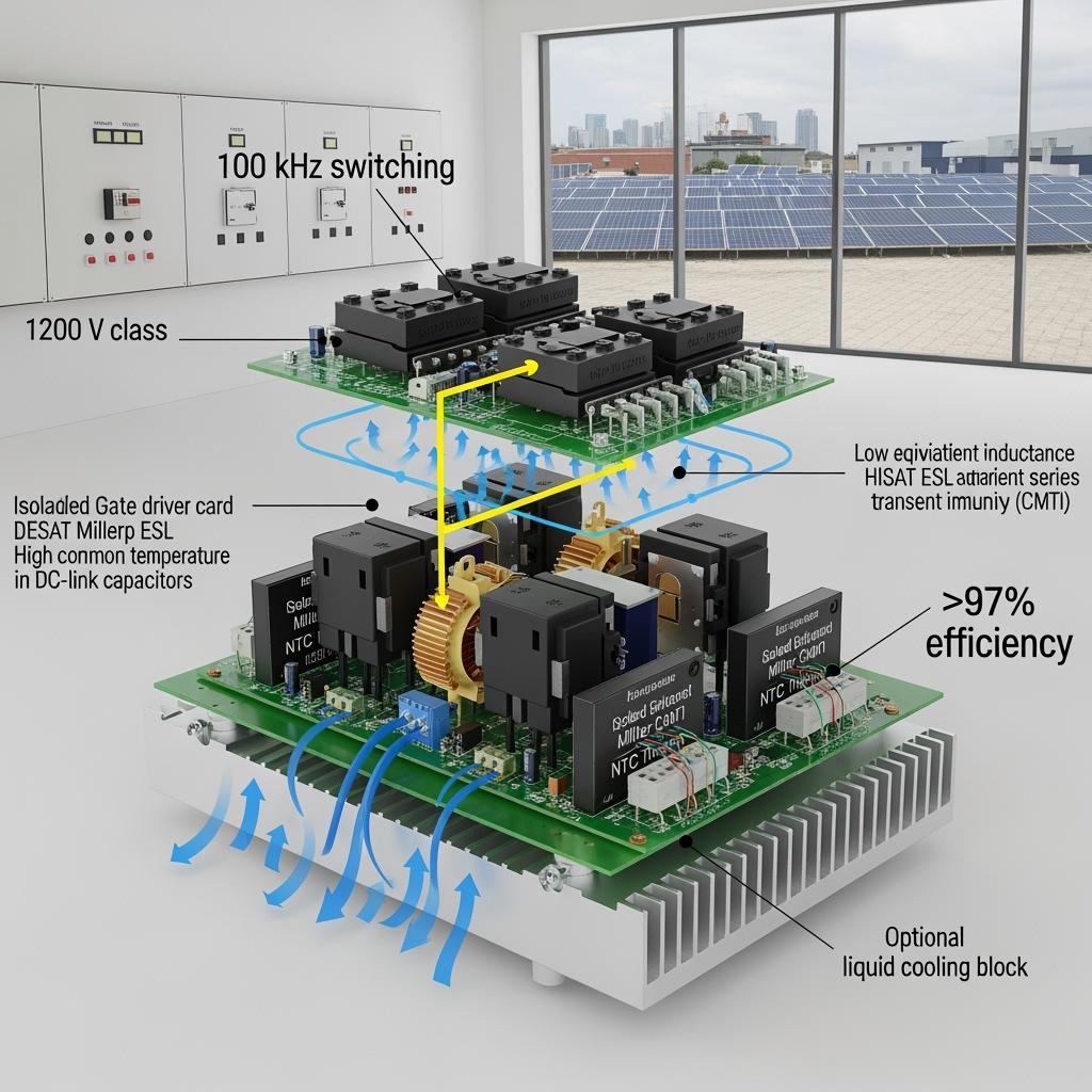
【Image prompt: detailed technical description】 Split-scene graphic: 1) SiC VFD driving an induction motor with FFT overlay showing low torque ripple; 2) Rooftop PV array feeding a SiC grid-tied inverter with efficiency curve; 3) Containerized BESS with SiC bidirectional stage and round-trip efficiency chart; add labels for switching frequency, Tj, and power density; photorealistic, 4K.
Selection and Maintenance Considerations
- Voltage/current headroom:
- Specify 20–30% electrical margin for sags/swells and overloads; validate motor insulation against dv/dt at the chosen switching frequency.
- Cooling:
- Model thermal paths at 40–45°C ambient; consider liquid cooling for >250 kW frames or high-altitude sites with reduced air density.
- EMC and wiring:
- Use laminated busbars, short DC loops, and proper shielding; long motor cables may require dV/dt or sine filters per IEC 61800-3.
- Protection coordination:
- Set DESAT thresholds, soft turn-off timing, and fast OCP; coordinate with upstream breakers/relays to prevent nuisance trips.
- Maintenance:
- Trend NTC temperatures, fan RPM, and capacitor ESR; schedule preventive service based on logged thermal cycles and run-hours.
- Environmental hardening:
- Conformal coating and positive-pressure enclosures in cement/textile; sealed connectors and IP ratings where relevant.
Industry Success Factors and Customer Testimonials
- Success factors:
- Accurate load profile and harmonic studies; transformer and cable assessment
- Pilot runs during peak summer to validate thermal and EMC margins
- Training on high-frequency layout, grounding, and maintenance best practices
- Integration with site SCADA for alarms and predictive analytics
- Testimonial (Operations Head, Karachi steel rolling auxiliary):
- “The SiC inverter stage improved drive stability and shaved energy costs. Our cabinets run cooler, and maintenance intervals have lengthened noticeably.”
Future Innovations and Market Trends
- 2025–2027 outlook:
- Broader adoption of 1700 V SiC for medium-voltage multi-level drives in cement and steel
- Intelligent inverter stages with embedded digital twins, condition monitoring, and cloud diagnostics
- Cost decline via 200 mm SiC wafers and local assembly, improving availability in Pakistan
- Enhanced coatings and heat spreaders (SSiC/RBSiC) for extreme dust/heat environments
Industry perspective:
“Wide-bandgap power semiconductors are moving mainstream for industrial and renewable inverters, with clear efficiency and density advantages accelerating adoption.” — IEEE Power Electronics Magazine, Market Watch 2024
Common Questions and Expert Answers
- Will higher switching frequency damage legacy motor insulation?
- We tune dv/dt via gate resistance and add dV/dt or sine filters for older motors. Our designs meet IEC 61800-3 EMC and motor insulation limits.
- Can SiC inverters handle Pakistan’s 220/400 V feeders and PEC-aligned protections?
- Yes. We design to local voltages and coordinate protection with site breakers/relays, aligning with NTDC Grid Code quality expectations.
- What efficiency gains should we expect for PV/BESS?
- PV weighted efficiencies typically exceed 97%; BESS round-trip can improve by ~2–3 percentage points versus silicon-based systems.
- What is a typical ROI?
- 18–30 months depending on duty cycle, tariffs, and cooling reductions; faster in 24/7 cement lines and data center/BESS deployments.
- How do you ensure reliability in 45°C dusty environments?
- High-Tj SiC devices, robust thermal design, conformal coating, and positive-pressure enclosures; ongoing diagnostics to preempt failures.
Why This Solution Works for Your Operations
SiC inverter power stages deliver the efficiency, control precision, and thermal resilience Pakistan’s industries need. Whether modernizing VFDs, scaling solar generation, or optimizing BESS, SiC reduces energy and cooling costs, enhances uptime under unstable grid conditions, and supports compliance with IEC and local standards—driving measurable lifecycle value.
Connect with Specialists for Custom Solutions
Engage Sicarb Tech to accelerate your inverter roadmap:
- 10+ years of SiC manufacturing expertise with Chinese Academy of Sciences backing
- Custom product development leveraging R-SiC, SSiC, RBSiC, SiSiC materials and advanced module packaging
- Technology transfer and factory establishment services—from feasibility studies to production line commissioning
- Turnkey solutions from material processing to finished inverter stages, including application engineering and compliance support
- Proven results with 19+ enterprises across demanding environments; rapid prototyping and pilot deployments
Book a free consultation for a site-specific performance and ROI assessment.
- Email: [email protected]
- Phone/WhatsApp: +86 133 6536 0038
Reserve Q4 2025 engineering slots now to secure lead times and deployment windows for peak season.
Article Metadata
- Last updated: 2025-09-11
- Next scheduled review: 2025-12-15
- Author: Sicarb Tech Application Engineering Team
- Contact: [email protected] | +86 133 6536 0038
- Standards focus: IEC 61800, IEC 62109, IEC 62477-1, IEC 61000; aligned with PEC practices and NTDC Grid Code quality criteria

About the Author: Sicarb Tech
We provide clear and reliable insights into silicon carbide materials, component manufacturing, application technologies, and global market trends. Our content reflects industry expertise, practical experience, and a commitment to helping readers understand the evolving SiC landscape.

Customizable SiC
You May Also Interest
-
![]()
Key SiC Exporters in Asia for International Trade
Key SiC Exporters in Asia for International Trade In the rapidly evolving landscape of advanced materials, silicon carbide (SiC) stands out as a material of unparalleled performance. Its exceptional properties make it indispensable across a spectrum of demanding industrial applications. For businesses seeking reliable and high-quality silicon carbide products, understanding the key players and regions…
-
![]()
SiC Substrates: Key to Electronic Device Advances
SiC Substrates: Key to Electronic Device Advances Introduction: The Pivotal Role of SiC Substrates In the rapidly evolving landscape of high-performance industrial applications, materials science plays a crucial role. Among advanced materials, silicon carbide (SiC) stands out, particularly in the form of SiC substrates. These substrates are not merely foundational layers; they are critical enablers…
-
![]()
SiC Innovation via University Research Links
SiC Innovation via University Research Links In the rapidly evolving landscape of advanced materials, custom silicon carbide (SiC) stands out as a true game-changer. Its unparalleled properties make it indispensable across a spectrum of demanding industrial applications, from the cutting edge of semiconductor manufacturing to the extreme environments of aerospace and nuclear energy. But what…