Silicon Carbide Schottky Diode Arrays for High-Efficiency PFC and Freewheeling in Industrial Drives and Energy Storage Converters

Share
Product Overview and 2025 Market Relevance
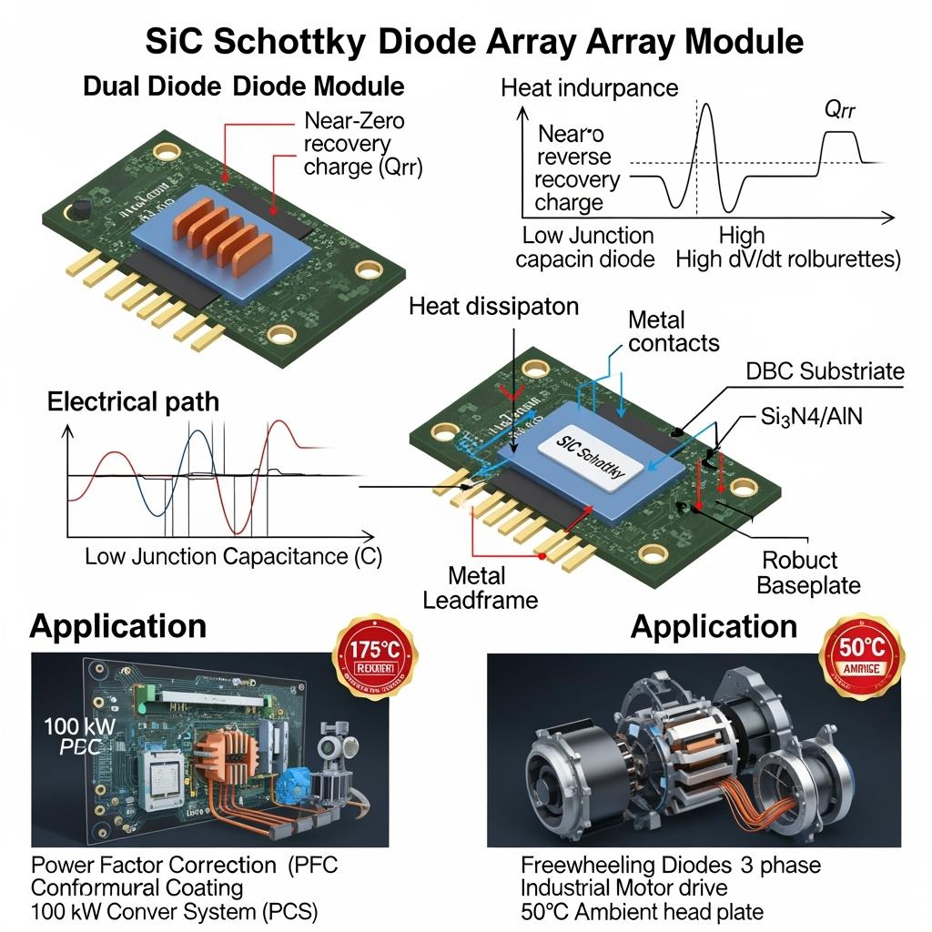
Silicon carbide (SiC) Schottky diode arrays are engineered for ultra-fast, low-loss rectification and freewheeling in power factor correction (PFC), DC/DC stages, and inverter legs across industrial drives and battery energy storage system (BESS) power conversion systems (PCS). Unlike silicon ultrafast or SiC PN junction diodes, SiC Schottky structures exhibit negligible reverse recovery charge (Qrr) and low junction capacitance (Cj), enabling high-frequency operation (50–200 kHz) with reduced switching loss and electromagnetic interference (EMI). In array configurations—dual common-cathode, common-anode, and full-bridge packs—they provide scalable current handling, compact footprints, and simplified thermal management.
For Pakistan’s textile, cement, steel, and emerging industrial sectors, 2025 priorities include raising PCS efficiency beyond 98%, shrinking cabinet volume, and maintaining stable operation on 11–33 kV feeders with voltage sags, harmonic distortion, and high ambient temperatures (often 45–50°C). SiC Schottky arrays directly address these goals by:
- Boosting PFC efficiency and reducing thermal load in front-end rectification.
- Minimizing diode-induced switching losses in freewheeling paths of inverter and drive stages.
- Improving system reliability through lower junction temperatures and robust 175°C operating capability.
Paired with SiC MOSFETs and optimized gate-drive strategies, these arrays enable 1.8–2.2× power density increases and support MTBF targets up to 200,000 hours in dusty, high-heat environments typical of industrial parks in Sindh, Punjab, and Balochistan.
Technical Specifications and Advanced Features
- Electrical characteristics
- Voltage classes: 650V, 1200V (typical for industrial PFC and inverter stages); higher classes available for specific MV designs
- Current ratings: 10–300 A per device; array options to meet higher current rails with parallel-friendly layouts
- Reverse recovery: Near-zero Qrr enabling high-frequency switching with minimal loss and EMI
- Junction capacitance: Low Cj with soft recovery profile for stable high dv/dt operation
- Forward voltage (VF): Optimized VF vs temperature for minimal conduction loss under high-current pulses
- Packaging and thermal design
- Array configurations: common-cathode/common-anode, dual/quad packs, and bridge arrays
- Interconnects: Low-inductance leadframes or laminated bus compatible terminals; Kelvin sense optional
- Substrates: Si3N4 for cycling strength or AlN for maximum thermal conductivity
- Die attach: Ag-sinter for superior thermal resistance and cycling endurance
- Reliability and environment
- Operating junction: -40°C to +175°C; derating curves provided
- Qualification: HTGB/HTRB, power cycling with defined ΔTj, and thermal shock per industrial norms
- Robustness: High surge current capability and dv/dt tolerance for hard-switching and freewheeling roles
- Integration and control
- Drop-in alternatives to silicon ultrafast diodes in PFC and inverter legs
- Compatible with SiC MOSFET switching at 50–200 kHz to reduce magnetics size and losses
- EMI-aware design reduces snubber requirements and filter volume
Performance Comparison for Industrial PFC and Freewheeling Stages
| Criterion | SiC Schottky diode arrays (optimized for 50–200 kHz) | Silicon ultrafast or PN diodes |
|---|---|---|
| Reverse recovery charge (Qrr) | Near-zero, minimal switching loss | High Qrr, significant loss and EMI |
| Operating frequency | High (50–200 kHz) with stable dv/dt | Limited by recovery and heating |
| Thermal performance | Lower junction temperature; smaller heat sinks | Hotter operation; larger cooling |
| Efficiency impact in PFC | +0.5–1.0% system gain typical | Lower, more snubbing needed |
| Reliability at high ambient | Strong at +175°C junction | Derating required; reduced lifetime |
Key Advantages and Proven Benefits with Expert Quote
- Efficiency uplift and thermal headroom: Near-zero Qrr slashes switching losses in PFC and inverter freewheeling, boosting overall PCS efficiency toward and beyond 98% while easing cooling demands.
- Compact, high-frequency operation: Supports 50–200 kHz switching, enabling smaller inductors and LCL filters—critical for space-constrained industrial parks.
- Robustness in harsh environments: High junction temperature capability and Ag-sinter/Si3N4 or AlN stacks resist ΔTj fatigue in dusty, hot facilities.
Expert perspective:
“SiC Schottky diodes practically eliminate reverse recovery loss, a dominant factor in high-frequency rectification and freewheeling, delivering measurable efficiency and size reductions.” — IEEE Transactions on Power Electronics, high-frequency rectification studies (https://ieeexplore.ieee.org)
Real-World Applications and Measurable Success Stories
- 100 kW PCS front-end in Punjab industrial park: Replacing silicon ultrafast diodes with 1200V SiC Schottky arrays raised PFC stage efficiency by ~0.8%, reducing heat sink mass by 30% and enabling a smaller cabinet footprint. System round-trip losses improved enough to shorten payback period.
- Textile mill variable-speed drives in Sindh: SiC freewheeling arrays minimized diode recovery spikes, reducing EMI-related trips and enabling higher switching frequency. Result: lower THD at the motor terminals and improved uptime during summer heat.
- BESS inverter in southern Pakistan: SiC arrays combined with SiC MOSFET legs reduced snubber network size and LCL filter volume, supporting ≥98% system efficiency and faster grid code acceptance.
Selection and Maintenance Considerations
- Device selection
- Voltage rating: 650V for LV stages, 1200V for HV DC links typical of industrial PCS; select with surge and margin considerations.
- Current and array topology: Size arrays for continuous and peak currents; consider parallel arrays with symmetrical layout.
- Thermal and mechanical
- Choose Si3N4 substrates for cycling robustness; AlN where peak heat flux is the limiter.
- Validate thermal path with CFD/FEA; maintain clean airflow and serviceable filter access in dusty plants.
- EMI and switching
- Coordinate with MOSFET gate resistance (Rg) and dv/dt shaping; lower Cj reduces ringing but verify layout parasitics.
- Reassess snubber needs—often downsized or eliminated with SiC Schottky arrays.
- Reliability
- Conduct power cycling with application-accurate ΔTj; confirm surge capability for abnormal events (inrush, faults).
- Log thermal sensor data for predictive maintenance in high-ambient seasons.
Industry Success Factors and Customer Testimonials
- Co-optimization with gate-drive and magnetics reduces EMI, shrinks filters, and speeds compliance on MV feeders.
- Parameter packs and commissioning guides reduce on-site tuning time.
Customer feedback:
“Upgrading to SiC Schottky arrays delivered an immediate PFC efficiency gain and let us cut cooling mass. Commissioning was smoother with fewer EMI issues.” — Engineering manager, C&I storage integrator
Future Innovations and Market Trends
- Higher-current, lower-capacitance arrays enabling even higher switching frequencies with reduced EMI.
- Integrated sensing (temperature, current estimation) to support predictive maintenance and digital twins.
- Localized module packaging and test capacity in Pakistan to shorten lead times and enhance after-sales service.
Common Questions and Expert Answers
- What is the typical efficiency gain from switching to SiC Schottky arrays in PFC?
Field results often show ~0.5–1.0% improvement at system level, with significant reductions in heat sink size. - Can SiC Schottky arrays reduce EMI issues?
Yes. Near-zero Qrr and low Cj reduce current spikes and ringing, often allowing smaller snubbers and filters. - Are arrays suitable for parallel operation?
Yes, with symmetric layout and thermal balance; arrays with matched characteristics and Kelvin options improve current sharing. - How do they perform at 45–50°C ambient?
High junction temperature capability and Ag-sinter/ceramic substrates maintain reliability; ensure adequate derating and filter maintenance. - Which applications benefit most?
Front-end PFC in PCS, freewheeling in inverter legs for industrial drives, boost and interleaved DC/DC stages in energy storage converters.
Why This Solution Works for Your Operations
SiC Schottky diode arrays deliver immediate, measurable gains where Pakistan’s industries need them most: front-end PFC efficiency, inverter freewheeling loss reduction, smaller thermal and filter hardware, and robust performance in hot, dusty conditions. Their near-zero Qrr and low Cj characteristics complement SiC MOSFET switches, lifting PCS efficiency toward ≥98% and enabling compact, reliable designs that meet evolving grid and plant requirements.
Connect with Specialists for Custom Solutions
Accelerate your efficiency roadmap with a partner delivering end-to-end SiC capability:
- 10+ years of SiC manufacturing expertise
- Chinese Academy of Sciences backing for device and packaging innovation
- Custom product development across R-SiC, SSiC, RBSiC, and SiSiC for thermal and structural optimization
- Technology transfer and factory establishment services for localized packaging and test
- Turnkey solutions from materials and epitaxy to arrays, modules, controls, and compliance
- Proven outcomes with 19+ enterprises achieving higher efficiency, reduced footprint, and faster commissioning
Request a free consultation and tailored diode array selection, thermal design, and EMI optimization plan:
- Email: [email protected]
- Phone/WhatsApp: +86 133 6536 0038
Secure 2025–2026 engineering and supply slots to de-risk projects, accelerate grid acceptance, and maximize ROI in PCS and industrial drive upgrades.
Article Metadata
Last updated: 2025-09-10
Next scheduled update: 2026-01-15

About the Author: Sicarb Tech
We provide clear and reliable insights into silicon carbide materials, component manufacturing, application technologies, and global market trends. Our content reflects industry expertise, practical experience, and a commitment to helping readers understand the evolving SiC landscape.

Customizable SiC
You May Also Interest
-
![]()
Europe’s Leading SiC Distributors for Easy Supply
Europe’s Leading SiC Distributors for Easy Supply In the rapidly evolving landscape of advanced materials, Silicon Carbide (SiC) stands out as a game-changer. Its unparalleled properties make it indispensable across a spectrum of high-performance industrial applications. For engineers, procurement managers, and technical buyers in industries ranging from semiconductors and automotive to aerospace and renewable energy,…
-
![]()
Silicon Carbide for Filtration: Revolutionizing Separation in Demanding Environments
In the ever-evolving landscape of industrial processing, the demand for highly efficient, durable, and reliable filtration solutions has never been greater. As industries push the boundaries of temperature, pressure, and chemical aggression, conventional filter materials often fall short. This is where custom silicon carbide (SiC) filtration products emerge as a game-changing technology. Renowned for their…
-
![]()
SiC Academic Research Insights for Industry Use
SiC Academic Research Insights for Industry Use In the relentless pursuit of performance and efficiency across demanding industrial sectors, silicon carbide (SiC) has emerged as a cornerstone material. Its exceptional properties—ranging from unparalleled hardness and wear resistance to superior thermal conductivity and chemical inertness—make it indispensable for high-stakes applications. This blog post delves into the…