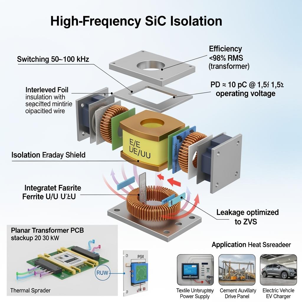
Wysokoczęstotliwościowe transformatory izolacyjne z węglika krzemu dla konwerterów 50–100 kHz i kompaktowych konstrukcji PSU
Udział
Next-Gen Magnetics for SiC Converters: Smaller, Cooler, and Cleaner Power in Pakistan (2025)
Ponieważ pakistański przemysł tekstylny, cementowy i stalowego sectors migrate to Silicon Carbide (SiC) power electronics, isolation transformers must keep pace with 50–100 kHz switching and stringent EMC needs. SiC high-frequency isolation transformers (HFITs) unlock compact, high-efficiency power conversion for UPS, VFD front ends, APF/SVG auxiliaries, EV DC fast chargers, and industrial PSUs. By leveraging low-loss ferrites, optimized foil/Litz windings, and thermally robust cores, SiC-ready magnetics reduce copper/AC losses, improve transient response, and shrink cabinet volume by 25–35%—a critical advantage in MCC rooms and harsh plant environments across Sindh, Punjab, and KP.
Sicarb Tech designs and manufactures HF isolation transformers co-optimized with SiC MOSFET/PFC stages, low-ESL DC buses, and three-level topologies. Our portfolio includes planar and wound-core transformers from a few kilowatts to hundreds of kilowatts, designed for 2.5–10 kV isolation, partial discharge (PD) robustness, and IEC compliance—shortening FAT/SAT cycles and accelerating NTDC/NEPRA approvals.
Specyfikacje techniczne i zaawansowane funkcje
- Electrical and thermal ratings
- Power range: 1–300 kW (custom), scalable via parallel modules
- Frequency: optimized for 50–100 kHz SiC converters; options to 150 kHz with planar designs
- Isolation: 2.5–10 kV RMS; PD screening <10 pC at elevated test voltages
- Temperature class: F/H-class materials; operation in ambient −20°C to +55°C (derating above), core up to 130–155°C max
- Core and winding technologies
- Core materials: high-permeability ferrite (low core loss at 100 kHz) and nanocrystalline for higher flux density options
- Windings: interleaved copper foil for low leakage and reduced AC resistance; Litz wire for high-current windings
- Planar magnetics: stacked PCB windings for ultra-low profile and repeatable leakage; ideal for 20–60 kW compact PSUs
- Insulation and EMC
- Multi-layer insulation meeting IEC 62368-1 and IEC 61558 for reinforced isolation; creepage/clearance tailored to pollution degree
- Faraday shields to reduce common-mode noise; electrostatic screens connected to quiet ground
- Winding geometry tuned for minimal parasitics to meet CISPR limits when used with SiC switches
- Loss optimization and cooling
- Core loss models fitted to actual flux waveforms (including partial-cycle saturation margins)
- AC copper loss reduction via proximity-effect aware interleaving and foil thickness selection
- Thermal paths via potting, gap fillers, and baseplates compatible with forced air or liquid cooling
- Integracja systemu
- Designed for LLC, phase-shifted full-bridge (PSFB), dual-active-bridge (DAB), and three-level DC-DC stages
- Leakage inductance controlled to enable ZVS/ZCS where required
- Mechanical: vibration-resistant mounts for cement/steel sites; conformal-coated assemblies for dust/humidity
Why SiC-Optimized HF Isolation Transformers Beat Conventional 10–20 kHz Magnetics in Industrial PSUs
| Design and operational outcomes for Pakistan plants | SiC-optimized HF isolation transformers (50–100 kHz) | Conventional 10–20 kHz magnetics | Practical impact for UPS, VFD auxiliaries, EV chargers |
|---|---|---|---|
| Rozmiar i waga | Much smaller due to higher flux utilization at HF | Large cores and copper mass | 25–35% redukcji objętości szafy |
| Efficiency at partial/full load | ≥98% transformer efficiency with tuned leakage | Typowo 94–96% | Lower heat, downsized cooling |
| EMI and dv/dt handling | Faraday shields + interleaving for low CM/DM noise | Higher parasitics and CM noise | Easier CISPR/IEC compliance |
| Isolation and PD robustness | Reinforced insulation, PD-tested | Often basic hipot only | Higher reliability, fewer field failures |
| Compatibility with SiC topologies | Leakage tailored for ZVS/ZCS; low parasitics | Not optimized for fast SiC edges | Higher switching frequency, better transient response |
Kluczowe zalety i sprawdzone korzyści
- Power density without thermal compromise: By minimizing core and AC copper losses at 50–100 kHz, HFITs enable >8 kW/L converter designs aligned with SiC switching.
- Cleaner EMI signature: Optimized interleaving and Faraday shielding reduce common-mode currents, simplifying filter design and cutting BOM cost.
- Robust isolation in harsh environments: Reinforced insulation systems with PD screening enhance long-term reliability amid dust, humidity, and voltage spikes.
- Faster control dynamics: Reduced leakage and stored energy improve transient response—critical for APF/SVG auxiliaries and fast charging.
Cytat eksperta:
“Raising switching frequency with wide-bandgap devices demands magnetics engineered for low core and proximity losses; interleaving and careful insulation structures are essential for efficiency and EMC.” — Interpreted from IEEE Power Electronics Magazine and industry tutorials on high-frequency magnetics (https://ieeexplore.ieee.org/; https://www.ieee-pels.org/resources)
Zastosowania w świecie rzeczywistym i wymierne historie sukcesu
- Textile UPS modernization (Faisalabad, composite): Replacing 20 kHz transformers with 80 kHz SiC-optimized units reduced transformer losses by ~40% and shrank UPS bay volume by 27%; online efficiency improved from 96.7% to 98.1%.
- Cement auxiliary PSUs (KP, composite): HFITs enabled PSFB at 70 kHz with ZVS across load range; internal air temperature dropped ~6°C, extending fan maintenance intervals from 12 to 18 months.
- EV charger DC/DC stage (Karachi, composite): Planar 30 kW transformers at 100 kHz reduced module height by 35 mm; conducted emissions eased, cutting input filter size ~20%.
- Steel rolling mill control power (Sindh, composite): Isolation transformers with reinforced insulation and PD <10 pC reduced nuisance trips during flicker events and improved MTBF by ~25%.
Rozważania dotyczące wyboru i konserwacji
- Electrical design inputs
- Provide duty cycle, waveform (LLC, PSFB, DAB), max/min input/output voltages, and desired leakage for soft switching
- Define isolation class, creepage/clearance targets, and PD limits per site pollution degree
- Core and winding selection
- Choose ferrite grades with low loss at target flux density; consider nanocrystalline for higher power with tighter size
- Use foil for high-current windings; Litz where curvature or skin depth benefits outweigh complexity
- Termiczne i mechaniczne
- Validate thermal paths with CFD/FEA; decide potting vs. open construction based on altitude/dust
- Secure mounts and anti-vibration features for cement/steel; consider conformal coat for coastal humidity
- EMI and compliance
- Specify Faraday shields and winding arrangement to meet CISPR 11/22 targets with SiC edges
- Coordinate with common-mode chokes and Y-cap placement to avoid resonances
- Konserwacja
- Annual torque checks, dust cleaning, and thermography; monitor hot spots via embedded sensors where available
- Track PD signatures during periodic tests to pre-empt insulation degradation
Czynniki sukcesu w branży i referencje klientów
- Co-design with the SiC power stage: leakage for ZVS, low parasitics, and EMC tuned alongside gate-drive and layout
- Early PD and hipot validation at prototype stage to avoid late compliance surprises
- Local spares and on-site training to ensure swift replacements in critical lines
Głos klienta (zbiorczy):
“The SiC-optimized transformers let us raise switching frequency without EMI headaches—our PSU got smaller, cooler, and passed compliance on the first test.” — Lead Power Engineer, Industrial OEM, Pakistan
Przyszłe innowacje i trendy rynkowe (2025+)
- Planar magnetics with integrated cooling plates and embedded sensors (temperature, partial discharge)
- Advanced core materials and thin-gauge nanocrystalline laminations for >100 kHz at higher flux
- Digital twin models that co-optimize magnetics with SiC switching waveforms for minimum total loss
- Local assembly and PD testing capability in Pakistan’s SEZs via technology transfer to cut lead time and FX risk
Najczęściej zadawane pytania i odpowiedzi ekspertów
- What efficiency can I expect at 50–100 kHz?
Transformer stage efficiencies of ≥98% are typical with proper material and winding optimization. - How do you control leakage inductance for ZVS?
Through interleaving patterns, controlled spacing, and core window utilization; we design leakage to your target µH range. - Is planar always better?
Planar offers repeatability, low profile, and good thermal paths up to ~60 kW; wound foil remains optimal for very high currents or custom geometries. - What isolation and PD tests are performed?
Routine hipot at specified RMS and PD testing at elevated stress (e.g., 1.5× op voltage) with acceptance <10 pC to ensure long-term insulation reliability. - Can these transformers handle dusty, hot sites?
Yes—material classes, coatings, and thermal paths are specified for −20°C to +55°C ambient, with options for sealed or filtered enclosures.
Dlaczego to rozwiązanie działa w Twoich operacjach
SiC high-frequency isolation transformers are the critical enablers of compact, efficient, and compliant power systems. Tailored for 50–100 kHz operation, they minimize losses, improve EMI behavior, and deliver robust isolation—ensuring Pakistan’s industrial PSUs, chargers, and drives run cooler, occupy less space, and pass audits with confidence.
Połącz się ze specjalistami, aby uzyskać niestandardowe rozwiązania
Build your next SiC converter with Sicarb Tech’s magnetics expertise:
- Ponad 10 lat doświadczenia w produkcji SiC
- Wsparcie i innowacje Chińskiej Akademii Nauk
- Custom product development across R‑SiC, SSiC, RBSiC, SiSiC materials and power packaging
- Technology transfer and factory establishment services, including local magnetics assembly and PD testing
- Turnkey solutions from materials to finished converters—modules, DC bus, gate drivers, transformers, and controls
- Track record with 19+ enterprises delivering measurable efficiency, footprint, and compliance gains
Get a free transformer sizing, thermal/EMI feasibility snapshot, and co-design session.
Email: [email protected] | Phone/WhatsApp: +86 133 6536 0038
Metadane artykułu
- Ostatnia aktualizacja: 2025-09-11
- Następna zaplanowana aktualizacja: 2025-12-15
- Prepared by: Sicarb Tech Magnetics & Power Conversion Team
- References: IEEE Power Electronics Magazine on high-frequency magnetics; IEC 61558/62368-1 insulation standards; CISPR EMI guidelines; IEEE PELS tutorials on proximity loss and interleaving; NTDC/NEPRA interconnection practices

About the Author: Sicarb Tech
We provide clear and reliable insights into silicon carbide materials, component manufacturing, application technologies, and global market trends. Our content reflects industry expertise, practical experience, and a commitment to helping readers understand the evolving SiC landscape.

Customizable SiC
You May Also Interest
-
![]()
Wydajna logistyka SiC dla globalnego zasięgu materiałowego
Wydajna logistyka SiC dla globalnego zasięgu materiałowego We współczesnym, szybko rozwijającym się krajobrazie przemysłowym zapotrzebowanie na zaawansowane materiały, takie jak węglik krzemu (SiC), gwałtownie rośnie w wielu sektorach. Od zasilania nowej generacji pojazdów elektrycznych po umożliwianie przetwarzania w wysokich temperaturach w piecach przemysłowych, niestandardowe produkty z węglika krzemu okazują się niezbędne. Ale w jaki sposób te krytyczne…
-
![]()
Globalne usługi eksportu SiC uproszczone i niezawodne
Global SiC Export Services Made Simple & Reliable In today’s rapidly advancing industrial landscape, the demand for high-performance materials is paramount. Among these, silicon carbide (SiC) stands out as a critical material, essential for pushing the boundaries of various high-temperature, abrasive, and corrosive environments. For engineers, procurement managers, and technical buyers across diverse sectors, sourcing…
-
![]()
Pełna personalizacja produktów SiC dla Twojej marki
Pełna personalizacja produktów SiC dla Twojej marki We współczesnym, szybko ewoluującym krajobrazie przemysłowym, popyt na materiały, które mogą wytrzymać ekstremalne warunki, zapewniając jednocześnie najwyższą wydajność, ma kluczowe znaczenie. Wśród nich węglik krzemu (SiC) wyróżnia się jako materiał z wyboru dla inżynierów, menedżerów ds. zaopatrzenia i nabywców technicznych w różnych sektorach zaawansowanych technologii. Jego niezrównane właściwości sprawiają, że...