Silicon Carbide Modular Cooling Systems with Integrated Heat Spreaders for Compact High-Power Density Designs
Share
Product Overview and 2025 Market Relevance
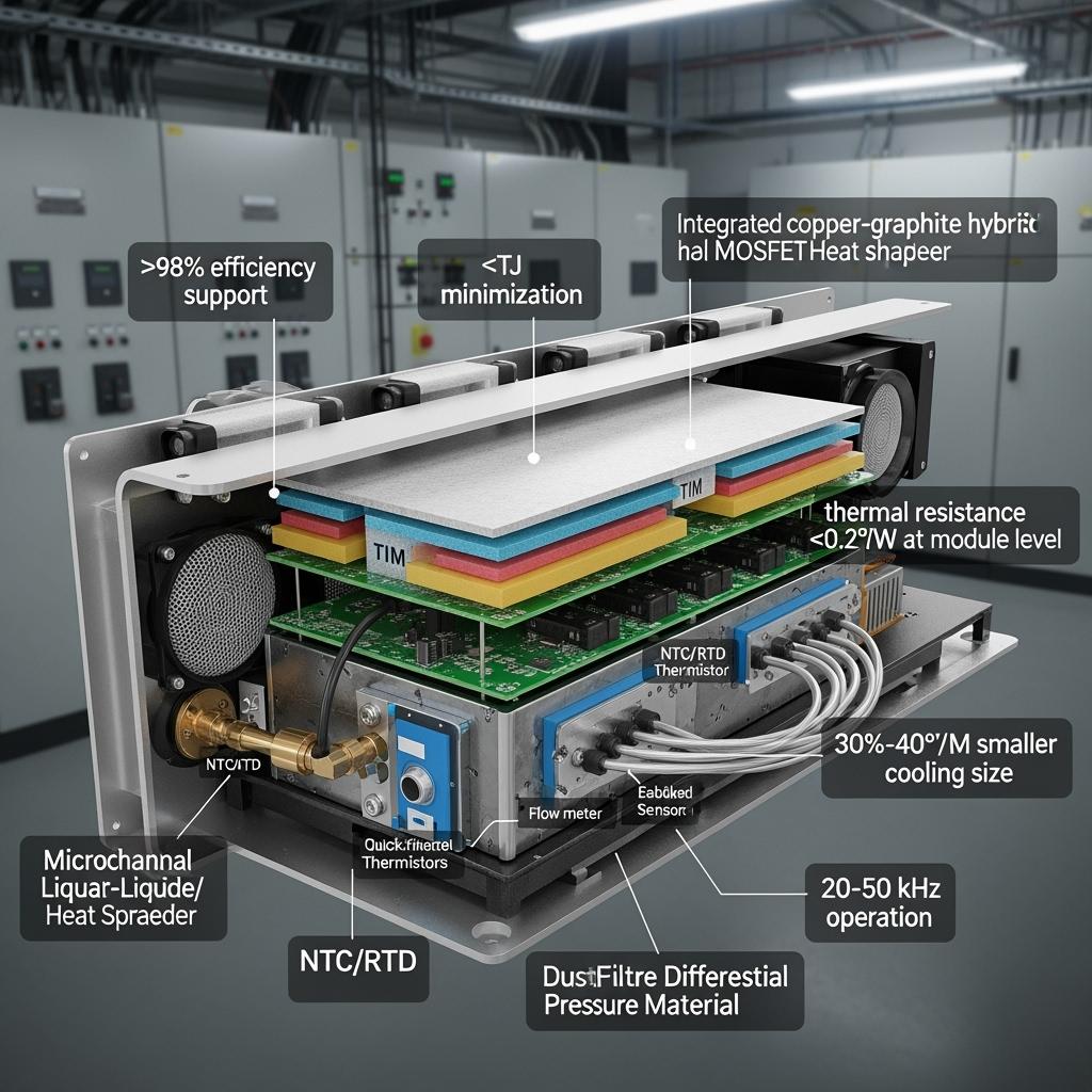
Silicon carbide (SiC) modular cooling systems with integrated heat spreaders are engineered to unlock compact, high-power-density designs across Pakistan’s textile, cement, steel, and emerging industrial sectors. By combining high-thermal-conductivity spreaders, liquid or sealed forced-air modules, and SiC-optimized thermal interfaces, these systems maintain device junction temperatures up to 175°C while sustaining rectification efficiencies above 98%. The result is 30%–40% smaller cooling hardware, stable operation in high-temperature and high-dust environments, and >50% reductions in thermally driven failure rates.
In 2025, plants in Punjab and Sindh are upgrading to SiC rectifiers, active front ends, and multi-pulse bridges to counter grid volatility and improve energy efficiency. Thermal constraints remain the limiting factor to power density and uptime. Modular cooling systems tailored for SiC—featuring AlN/Si3N4 substrate stacks, sintered interfaces, and integrated spreaders fabricated from copper composite or graphite-based materials—deliver uniform heat flux distribution across device clusters, enabling tighter cabinet layouts and higher current density. These systems integrate sensors for flow, temperature, and differential pressure, expose KPIs to SCADA via OPC UA/MODBUS/PROFINET, and align with IEC 62477-1 (safety) and IEC 61000 (EMC) deployment practices while contributing to ISO 50001 and ISO 14001 reporting.
Technical Specifications and Advanced Features
- Thermal architecture
- Integrated heat spreaders: Copper-molybdenum, copper-graphite, or pyrolytic graphite composites for high in-plane conductivity and uniform heat distribution
- Ceramic substrate pairing: AlN/Si3N4 stacks with active metal brazed copper for low thermal resistance and CTE compatibility with SiC dies
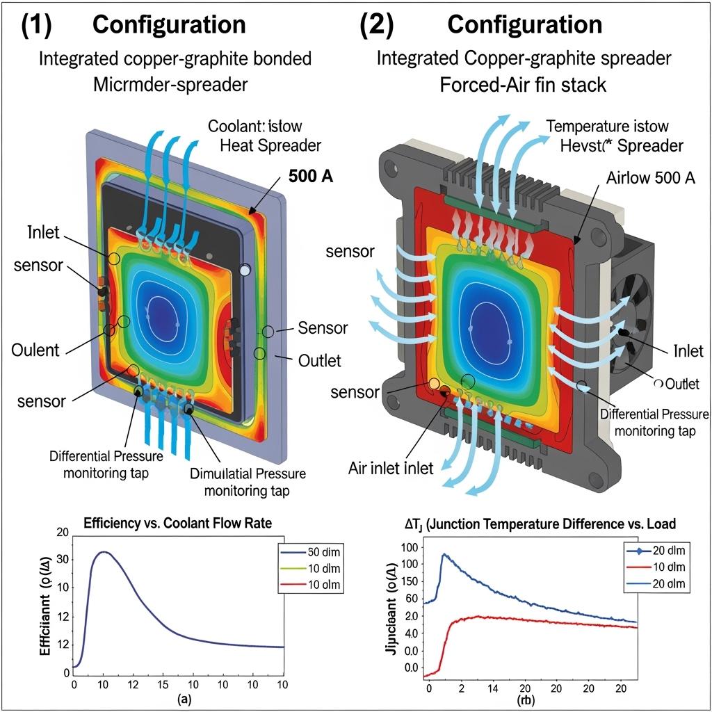
- Cold plate technologies: Microchannel, pin-fin, or skived-fin liquid plates with optimized pressure drop; sealed high-efficiency forced-air alternatives for sites avoiding liquid loops
- Module-level thermal resistance: <0.2°C/W with validated TIMs and clamping schemes
- Mechanical and environmental
- Enclosures: IP54+ with positive-pressure filtration to resist dust; corrosion-resistant coatings for humid or chemically aggressive areas
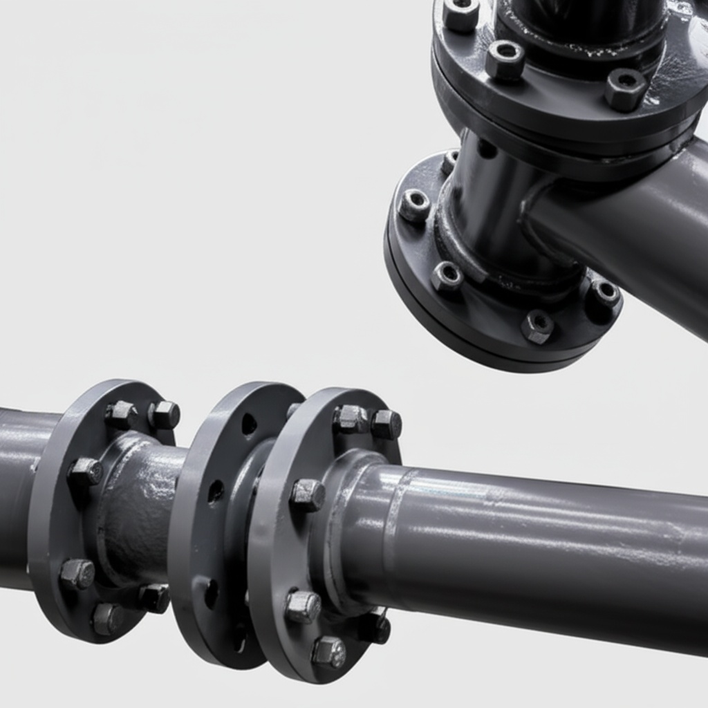
- Manifolds: Quick-disconnect, dripless couplings; flow balancing for parallel module strings; vibration isolation mounts for mining and steel environments
- Serviceability: Modular drawer or plate designs enabling hot-side access; standardized gasket kits and torque specs
- Sensing, analytics, and controls
- Sensors: NTC/RTD temperature, coolant flow, inlet/outlet temperature, and differential pressure for fouling detection
- Interfaces: OPC UA, MODBUS TCP, PROFINET, EtherNet/IP for SCADA/MES/CMMS data logging and alarms
- Predictive maintenance: Thermal impedance trending, coolant ΔP rise rate, and TIM degradation indicators
- Compliance and documentation
- Standards alignment: IEC 62477-1 safety documentation, IEC 61000 EMC-friendly layouts
- Reporting: KPI exports supporting ISO 50001 energy and ISO 14001 environmental programs
Performance Advantages for Compact High-Power Density Designs
| Operations and design outcome | SiC Modular Cooling with Integrated Heat Spreaders | Conventional Cooling without Integrated Spreaders |
|---|---|---|
| Thermal resistance and ΔTj | <0.2°C/W with uniform heat flux; minimized hot spots | Higher localized ΔTj; risk of thermal runaway |
| Cooling footprint | 30%–40% smaller skids/heat exchangers | Larger heat sinks and HVAC loads |
| Power density | Enables >8 kW/L cabinet designs | Lower density; larger cabinets |
| Reliability and lifetime | >50% reduction in thermally driven failures | Frequent maintenance due to thermal cycling damage |
| Maintenance interval | Once every 2 years (condition-based) | Twice per year or more |
| Energy efficiency | Supports >98% rectification efficiency | Higher thermal losses reduce net efficiency |
Key Advantages and Proven Benefits with Expert Insight
- Uniform heat spreading: Integrated spreaders equalize temperature across densely packed SiC modules, enabling higher current density and tighter busbar layouts.
- Reduced cooling infrastructure: Efficient heat extraction lowers pump/fan power and skid size, delivering immediate energy savings.
- Long-term reliability: CTE-compatible stacks and stable TIMs reduce solder/sinter fatigue, extending service life beyond 15 years in continuous duty.
- Environmental resilience: Positive-pressure, IP-rated designs withstand dust, humidity, and vibration typical of cement, steel, and mining operations.
Expert quote:
“Advanced cooling with high-conductivity spreaders is essential to harness SiC’s high switching speeds and current density without compromising reliability.” — IEEE Power Electronics Magazine, Thermal Management for WBG Converters (2023)
Authority reference:
“By 2025, thermal solutions co-designed with SiC packaging are a primary driver of system-level efficiency gains and power density in industrial converters.” — Yole Group, Power SiC Market Monitor (2024)
Real-World Applications and Measurable Success Stories
- Cement clinker workshop rectifiers
- Result: Integrated spreader plus microchannel plate reduced module-to-coolant thermal resistance below 0.2°C/W; rectification efficiency increased from 92.3% to 98.1%; cooling skid size lowered by ~35%; annual electricity savings exceeded 120,000 USD; continuous operation achieved 8,760 hours in a Karachi facility.
- Steel melt shop AFE and DC drives
- Result: Lower ΔTj during high-load transients; reduced transformer and cabinet hot spots; maintenance intervals extended to 24 months with predictive coolant monitoring.
- Mining crushers and conveyors
- Result: Sealed forced-air modules with spreaders maintained stable temperatures in dusty environments; fewer thermal trips and improved uptime.
Selection and Maintenance Considerations
- Configuration selection
- Liquid cooling: Choose microchannel or pin-fin plates for highest heat flux near furnaces/kilns; verify coolant chemistry (glycol ratios, corrosion inhibitors).
- Sealed forced-air: Use where liquids are restricted; specify high-static-pressure fans and fin stacks with anti-fouling coatings.
- Heat spreader material choice
- Copper-molybdenum or copper-graphite for balanced through-plane and in-plane conductivity
- Pyrolytic graphite inserts where maximum in-plane spreading is required
- Ensure CTE compatibility with ceramic substrates and baseplates
- TIM and clamping
- Select TIMs rated for 175°C with low pump-out; enforce uniform pressure via calibrated hardware; maintain surface flatness and roughness specs.
- Sensing and analytics
- Trend coolant ΔP to detect fouling; monitor inlet/outlet ΔT; correlate thermal impedance changes with TIM aging.
- Preventive maintenance (24 months)
- Flush coolant and replace filters; re-torque clamps; verify sensor calibration; inspect for corrosion/debris; update control firmware.
Industry Success Factors and Customer Testimonials
- Success factors: Early thermal-FEA co-design, CFD-driven manifold optimization, EMC-aware busbar routing, and robust filtration strategy for dust-prone sites.
- Customer voice: “Modular cooling with integrated spreaders stabilized our thermal margins and allowed a denser cabinet layout without increasing HVAC.” — Electrical Maintenance Lead, integrated steel producer in Punjab.
Future Innovations and 2025+ Market Trends
- Next-gen spreaders: Graphite-metal hybrids and vapor chamber variants tailored for high-g shock and vibration in heavy industry.
- Embedded sensing: On-plate temperature arrays and micro-flow sensors for granular thermal maps and predictive diagnostics.
- Local manufacturing: Technology transfer to establish cooling plate machining, brazing, and test lines in Pakistan to shorten lead times.
- Sustainability: Lower pumping and fan energy directly supports ISO 50001 KPIs and reduces site carbon intensity.
Industry outlook:
“Thermal innovations are indispensable for achieving compact, efficient industrial converters—particularly where ambient temperatures and dust are challenging.” — International Energy Agency, Technology Perspectives (2024)
Common Questions and Expert Answers
- How do integrated heat spreaders improve reliability?
- They distribute heat laterally, reducing hot spots and ΔTj swings that cause solder/sinter fatigue and device stress.
- When should I choose liquid cooling over sealed forced-air?
- Use liquid cooling for highest heat flux or near high ambient heat sources; sealed forced-air suits sites with strict liquid restrictions.
- What data should be monitored for predictive maintenance?
- Coolant differential pressure, inlet/outlet temperatures, module temperatures, and calculated thermal impedance trends.
- Can these modules retrofit existing rectifier cabinets?
- Yes. Adapter plates, manifold kits, and busbar interfaces support drop-in retrofits while preserving cabinet envelopes.
- What are typical lead times?
- Standard modules: 6–10 weeks; customized spreaders/manifolds/enclosures: 10–14 weeks, with on-site commissioning in 1–2 weeks.
Why This Solution Works for Your Operations
SiC modular cooling systems with integrated heat spreaders directly address the primary barrier to higher power density: heat extraction. By minimizing thermal resistance, equalizing temperatures, and enabling 30%–40% reductions in cooling size, they support >98% efficiency and high current density, improve uptime by reducing thermal trips, and extend service intervals to 24 months. For Pakistan’s heavy-duty sectors, they provide a practical, retrofit-friendly path to higher productivity and lower total cost of ownership.
Connect with Specialists for Custom Solutions
Deploy compact, reliable SiC systems with thermal solutions engineered end-to-end for your mission profile.
- 10+ years of SiC manufacturing expertise
- Chinese Academy of Sciences backing and innovation
- Custom product development across R-SiC, SSiC, RBSiC, and SiSiC
- Technology transfer and factory establishment services
- Turnkey solutions from material processing to finished products
- Track record with 19+ enterprises
Request a free consultation, thermal stack review, and ROI model tailored to your plant. Reserve engineering capacity for CFD/FEA, manifold design, and pilot installation.
- Email: [email protected]
- Phone/WhatsApp: +86 133 6536 0038
Recommended next steps: Share cabinet dimensions, allowable pressure drop, coolant chemistry, target load profiles, and ambient conditions; schedule a thermal audit; plan a pilot retrofit with acceptance KPIs.
Article Metadata
- Last updated: 2025-09-12
- Next scheduled update: 2026-03-31
- References: IEEE Power Electronics Magazine (2023) Thermal Management for WBG Converters; Yole Group Power SiC Market Monitor (2024); International Energy Agency Technology Perspectives (2024)

About the Author: Sicarb Tech
We provide clear and reliable insights into silicon carbide materials, component manufacturing, application technologies, and global market trends. Our content reflects industry expertise, practical experience, and a commitment to helping readers understand the evolving SiC landscape.

Customizable SiC
You May Also Interest
-
![]()
SiC Substrates: Key to Electronic Device Advances
SiC Substrates: Key to Electronic Device Advances Introduction: The Pivotal Role of SiC Substrates In the rapidly evolving landscape of high-performance industrial applications, materials science plays a crucial role. Among advanced materials, silicon carbide (SiC) stands out, particularly in the form of SiC substrates. These substrates are not merely foundational layers; they are critical enablers…
-
![]()
SiC Innovation via University Research Links
SiC Innovation via University Research Links In the rapidly evolving landscape of advanced materials, custom silicon carbide (SiC) stands out as a true game-changer. Its unparalleled properties make it indispensable across a spectrum of demanding industrial applications, from the cutting edge of semiconductor manufacturing to the extreme environments of aerospace and nuclear energy. But what…
-
![]()
Next-Gen SiC Wafers for Power Electronics Excellence
Next-Gen SiC Wafers for Power Electronics Excellence Introduction: The Pivotal Role of SiC Wafers in Modern Power Electronics The relentless pursuit of higher efficiency, increased power density, and superior performance in power electronic systems has spotlighted silicon carbide (SiC) as a transformative material. SiC wafers, the foundational substrates for SiC-based power devices, are at the…