>98% 효율 및 고전류 밀도를 갖춘 전해 정류 시스템용 탄화규소 전력 스테이지
공유
제품 개요 및 2025년 시장 관련성
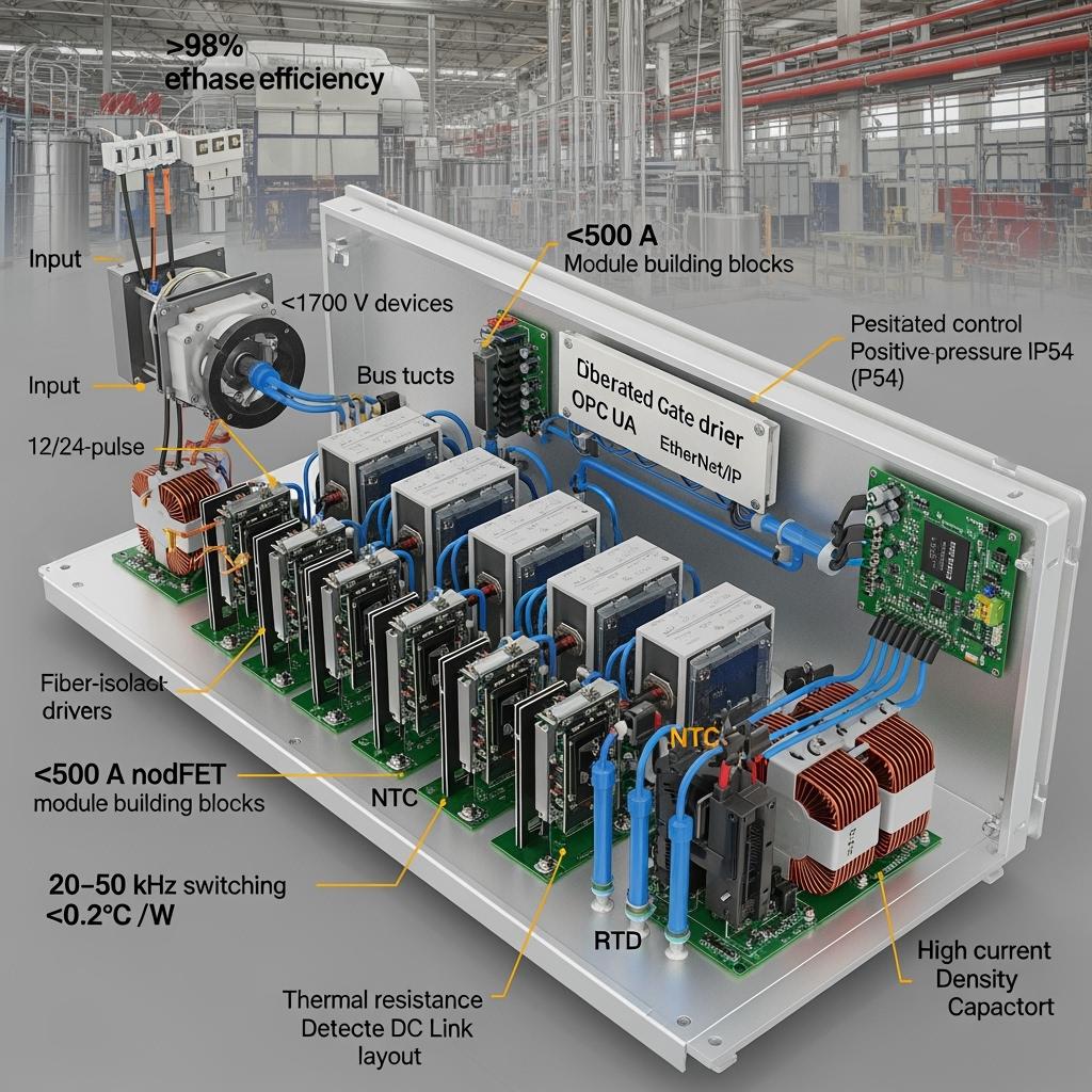
Silicon carbide (SiC) power stages engineered for electrolytic rectification deliver >98% efficiency, high current density, and robust thermal margins for Pakistan’s textile, cement, 강철, and emerging industrial sectors. These power stages integrate SiC high-power Schottky diodes, SiC MOSFET bridges or active front ends (AFE), high-thermal-conductivity ceramic substrates, and modular cooling systems to support continuous heavy-duty operation with minimal downtime.
In 2025, producers in Punjab and Sindh face grid volatility, rising electricity tariffs, and aging rectifier assets. SiC power stages address these constraints by enabling 20–50 kHz operation, stable performance at junction temperatures up to 175°C, and compact thermal designs that reduce cooling infrastructure by 30%–40%. Plants report 10%–15% annual energy savings and >50% reduction in failure rates, while maintaining power quality and meeting compliance requirements. Documentation aligns with IEC 62477-1 (safety), IEC 61000 (EMC), and IEC 60747 (semiconductor devices), and data integration supports ISO 50001 energy and ISO 14001 environmental programs. Power stages are delivered as modular building blocks for electrolytic aluminum, electroplating, electrowinning, DC drives, and furnace rectifiers, with options for multi-pulse architectures and AFE-based harmonic mitigation.
기술 사양 및 고급 기능
- 전기 정격 및 토폴로지
- Input: 400–690 VAC three-phase, compatible with multi-pulse transformer secondaries
- Output: High-current DC rails for electrolytic cells and furnace supplies
- Device classes: SiC MOSFETs and high-power SiC Schottky diodes, ≥1700 V
- Current capability: ≥500 A per module; scalable in parallel to kA-class outputs with current sharing
- Rectification strategies: 6/12/24-pulse passive reduction; optional AFE for low THDi and near-unity power factor
- 스위칭 및 제어
- Frequency: 20–50 kHz to minimize ripple and reduce passive size
- Control features: Soft-start/pre-charge, sag/swell ride-through, current balancing, and ripple optimization for electrolytic stability
- Interfaces: MODBUS TCP, PROFINET, EtherNet/IP, DNP3, OPC UA with structured data models for SCADA/MES/CMMS
- 열 및 기계적 설계
- Junction temperature range: -55°C to 175°C device capability
- Module-level thermal resistance: <0.2°C/W using AlN/Si3N4 substrates and optimized baseplates
- Cooling: Liquid cooling or sealed high-efficiency forced-air; positive-pressure IP54 cabinet designs for dust-prone sites
- Layout: Laminated busbars and low-inductance loops for reduced EMI; vibration-resistant mounts
- 보호 및 진단
- Fast desaturation/short-circuit protection (AFE), surge suppression, DC link crowbar options
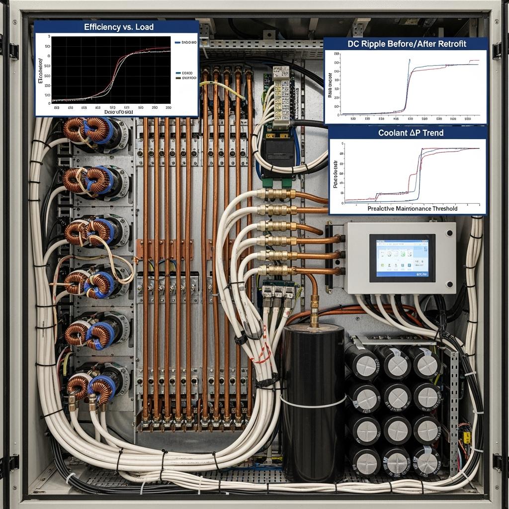
- Sensor suite: NTC/RTD temperature, DC ripple, input harmonics, coolant flow and differential pressure
- Analytics: Leakage and Vf tracking, dynamic Rds(on), capacitor ESR trending, thermal impedance monitoring for predictive maintenance
- Compliance and documentation
- Standards: IEC 62477-1, IEC 61000 series, IEC 60747 device data
- Programs: KPI logging for ISO 50001 and ISO 14001; audit-ready test and calibration records
Performance Advantages for Electrolytic Rectification and High Current Density
| Operations outcome | SiC Power Stages for Electrolytic Rectification | Conventional Silicon Rectifier Stages |
|---|---|---|
| Rectification efficiency | >98% across wide load range | 일반적 90%–94% |
| Current density and footprint | Higher density enabling >8 kW/L and smaller cabinets | Lower density, large footprint |
| 열 관리 | 30%–40% smaller cooling systems; stable 175°C junction capability | Larger cooling hardware; derating at elevated temps |
| Reliability and uptime | >50% failure-rate reduction; 24-month maintenance intervals | Higher failure rates; semi-annual maintenance |
| 전력 품질 | Low ripple and optional AFE for low THDi and high PF | Higher ripple; power factor correction required |
| 투자 회수 기간 | 에너지 및 OPEX 절감을 통해 2–3년 | Longer due to higher losses and maintenance |
전문가의 통찰력과 함께 주요 장점 및 입증된 이점
- High-efficiency conversion: Negligible reverse recovery from SiC diodes and low switching loss from SiC MOSFETs sustain >98% efficiency, directly lowering OPEX.
- High current density: Optimized ceramic substrates and laminated busbars enable compact, kA-class outputs with controlled thermal gradients.
- Electrolytic process stability: Reduced ripple and fast dynamic response improve product quality and cell life in electrowinning and plating.
- Harsh-environment resilience: IP-rated enclosures, conformal-coated boards, and robust cooling guard performance against dust and heat.
전문가 인용문:
“SiC power stages cut losses and improve thermal headroom, enabling stable high-current electrochemical processes while shrinking system size.” — IEEE Power Electronics Magazine, Wide Bandgap for Industrial DC Conversion (2023)
권위 참조:
“By 2025, the economics of SiC in high-current rectification are compelling, with system-level energy savings and reliability gains driving adoption.” — Yole Group, Power SiC Market Monitor (2024)
실제 응용 분야 및 측정 가능한 성공 사례
- Electrolytic process hall upgrade (cement-associated metals recovery)
- Result: Overall rectification efficiency raised from 92.3% to 98.1%; kA-class output stabilized with lower ripple; cooling skid footprint reduced by ~35%; electricity savings exceeded 120,000 USD annually; continuous operation increased to 8,760 hours in a Karachi facility.
- Steel plant furnace DC supply
- Result: SiC AFE improved power factor and reduced THDi; fewer transformer hot spots; maintenance intervals extended to 24 months.
- Textile auxiliary plating lines and SMPS front ends
- Result: Higher frequency operation (20–30 kHz) reduced passive components; cabinet temperatures dropped; improved uptime under dusty conditions.
선택 및 유지 관리 고려 사항
- Core design choices
- Pulse strategy: 12/24-pulse for passive harmonic reduction; add AFE if near-unity power factor or regenerative capability is needed.
- Device selection: ≥1700 V SiC MOSFETs and Schottky diodes sized for surge, ripple, and thermal headroom; ensure proper SOA and short-circuit coordination.
- Thermal engineering
- Use high-thermal-conductivity ceramics (AlN/Si3N4) and validated TIMs; model coolant flow to maintain ΔT within targets; consider liquid cooling near furnaces/kilns.
- EMC 및 배선
- Apply low-inductance busbars, dv/dt filters, shielded control harnesses, and compliant grounding/earthing to meet IEC 61000 limits.
- Service plan (24 months)
- Inspect/retorque busbar joints, verify capacitor ESR, check coolant chemistry/filters, recalibrate sensors, and update firmware; trend thermal impedance and Rds(on) for early warnings.
산업 성공 요인 및 고객 사용후기
- Success factors: Power-quality assessment, transformer vector group alignment, thermal and EMI co-design, rigorous factory acceptance testing, and operator training.
- Customer voice: “The SiC power stage stabilized our high-current rectifiers, cut cooling energy, and simplified compliance reporting.” — Electrical Manager, integrated steel producer in Punjab.
미래 혁신 및 2025+ 시장 동향
- Higher-voltage pathways: 3.3 kV SiC devices to simplify series stacking and reduce insulation complexity in medium-voltage rectifiers.
- Co-packaged power stages: Tighter integration of MOSFET/diode dies and gate drivers to reduce parasitics and improve current sharing.
- Embedded intelligence: On-module sensors and health analytics for continuous lifetime estimation and predictive maintenance.
- Localization: Technology transfer for local assembly, testing, and service in Pakistan to reduce lead times and adapt to site conditions.
산업 전망:
“Front-end DC conversion efficiency and reliability are critical levers for industrial decarbonization, with SiC at the core of next-generation rectifiers.” — International Energy Agency, Technology Perspectives (2024)
일반적인 질문 및 전문가 답변
- How do SiC power stages achieve >98% efficiency?
- Low switching and conduction losses from SiC MOSFETs and Schottky diodes, coupled with optimized magnetics and high-thermal-conductivity substrates, minimize total losses.
- What current levels can be supported?
- Modules rated ≥500 A can be paralleled with equalization strategies to reach kA-class outputs for electrolytic cells and furnaces.
- Do I need an AFE or is multi-pulse enough?
- 12/24-pulse often meets THD targets; select AFE for stricter THDi limits, near-unity power factor, or regenerative operation.
- What is the typical deployment timeline?
- Standard builds: 6–10 weeks; custom ratings/enclosures: 10–14 weeks; commissioning and acceptance testing typically within 1–2 weeks on site.
- How is reliability ensured in dust and heat?
- IP54+ enclosures, positive-pressure filtration, conformal coating, liquid cooling, and predictive diagnostics preserve thermal margins and uptime.
이 솔루션
SiC power stages provide the efficiency, current density, and ruggedness required for electrolytic rectification in Pakistan’s heavy industries. They enable >98% efficiency, reduce cooling infrastructure by 30%–40%, cut failure rates by more than 50%, and support stable, continuous operation at elevated temperatures. With modular integration, power quality compliance, and predictive maintenance, these stages shorten payback to 2–3 years and future-proof rectifier fleets.
맞춤형 솔루션을 위해 전문가와 연결
Scale your electrolytic rectification performance with end-to-end SiC expertise and turnkey delivery.
- 10년 이상의 SiC 제조 전문 지식
- 중국 과학 아카데미의 지원 및 혁신
- R-SiC, SSiC, RBSiC 및 SiSiC 전반에 걸친 맞춤형 제품 개발
- 기술 이전 및 공장 설립 서비스
- 재료 처리부터 완제품까지 턴키 솔루션
- 19개 이상의 기업과 함께한 실적
Request a free consultation, detailed thermal/electrical design review, and a plant-specific ROI model. Reserve engineering capacity for harmonic studies, thermal simulation, and pilot deployment.
- 이메일: [email protected]
- 전화/왓츠앱: +86 133 6536 0038
Recommended next steps: Share single-line diagrams, transformer vector groups, electrolytic cell duty profiles, cooling constraints, and harmonic limits; schedule a power-quality audit; plan a pilot power stage with measurable KPIs.
문서 메타데이터
- 최종 업데이트: 2025-09-12
- 다음 예정 업데이트: 2026-03-31
- References: IEEE Power Electronics Magazine (2023) Wide Bandgap for Industrial DC Conversion; Yole Group Power SiC Market Monitor (2024); International Energy Agency Technology Perspectives (2024)

About the Author: Sicarb Tech
We provide clear and reliable insights into silicon carbide materials, component manufacturing, application technologies, and global market trends. Our content reflects industry expertise, practical experience, and a commitment to helping readers understand the evolving SiC landscape.