LCL Filter Solutions for Medium-Voltage Grid Interconnection Optimized for Low THD in SiC-Based Inverters
Share
Product Overview and 2025 Market Relevance
LCL filter solutions engineered for silicon carbide (SiC) inverters provide low total harmonic distortion (THD), robust grid compliance, and compact size for distribution-level interconnections at 11–33 kV. By leveraging high-frequency operation (50–150 kHz), advanced magnetic materials, and optimized damping, these filters enable Pakistan’s textile, cement, and steel sectors to deploy high-efficiency PV inverters and industrial drives that maintain ≥98.5% system efficiency and up to 2× power density while operating reliably in hot, dusty environments.
In 2025, Pakistan’s accelerated adoption of string and centralized photovoltaic systems in industrial parks and commercial sites demands compact, dust-tolerant, and maintainable solutions. SiC’s fast switching reduces passive component size, but it elevates EMI and resonance challenges at the grid interface. Purpose-built LCL filters—integrating differential-mode inductors, grid/converter-side chokes, filter capacitors, and damping networks (passive or active)—deliver low THD under variable grid impedance, support fault ride-through strategies, and sustain performance at 45–50°C ambient. Designs optimized for MV step-up transformers and 3-level/5-level SiC topologies minimize losses and ensure stable control-loop interaction.
Technical Specifications and Advanced Features
- Frequency and topology alignment:
- Optimized for SiC switching at 50–150 kHz, compatible with 2-level and multi-level inverters
- Resonance frequency tuned between control bandwidth and switching frequency to avoid interaction and excessive ripple
- Magnetic design:
- Low-loss ferrite and nanocrystalline cores with interleaved/litz windings to minimize AC resistance
- Thermal class up to 125–155°C insulation systems; reduced temperature rise in 45–50°C ambient
- Capacitor and damping network:
- Polypropylene film capacitors with low ESR; dedicated discharge/bleed paths
- Passive damping (R or R-L series/parallel) or active damping via control to reduce power loss and size
- THD and compliance:
- Target grid-side current THD below typical utility thresholds with varying grid impedance and transformer leakage
- Integrated EMI stage (differential/common-mode) to reduce conducted emissions
- Environmental robustness:
- IP55 cabinet options with washable pre-filters; wide-fin thermal path for dust resistance
- Temperature and vibration monitoring for predictive maintenance
- Instrumentation and control:
- Voltage and current sensors at converter and grid nodes for real-time THD estimation and active damping control
- Interfaces for inverter controller (CAN/Modbus) and data logging
Descriptive Comparison: SiC-Optimized LCL Filters vs Conventional Low-Frequency Filters
| Criterion | SiC-optimized LCL filter for 50–150 kHz | Conventional low-frequency L/C filter |
|---|---|---|
| Size and weight | Compact; supports 30–40% cooling volume reduction | Bulky magnetics and capacitors |
| THD at MV interconnection | Low THD with tuned resonance and damping | Higher THD unless oversized |
| Core and copper losses | Minimized via high-frequency materials and litz | Elevated at higher ripple frequencies |
| Control interaction | Designed for active/passive damping with SiC loops | Limited interaction handling |
| Dust/thermal resilience | Dust-resistant airflow, thermal sensors | Often requires larger airflow and space |
Key Advantages and Proven Benefits with Expert Quote
- Low THD with compact footprint: High-frequency design reduces L and C values, delivering compliance-ready harmonic performance in smaller cabinets.
- Improved efficiency: Low-loss cores, optimized windings, and right-sized capacitors support ≥98.5% system efficiency targets.
- Robust under grid variability: Tuned resonance and damping strategies maintain stability across a range of grid impedances and transformer characteristics.
- Environmental readiness: Dust-resistant enclosures and thermal monitoring preserve performance in Pakistan’s hot, dusty sites.
Expert perspective:
“LCL filters paired with wide bandgap inverters can achieve stringent harmonic limits with substantially reduced passive size, provided resonance and damping are co-designed with the control system.” — IEEE Power Electronics applications guidance (ieee.org)
Real-World Applications and Measurable Success Stories
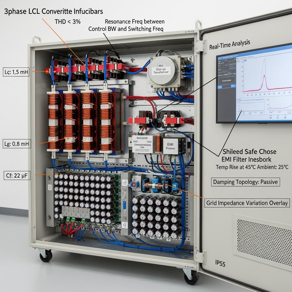
- MV PV inverters (southern Pakistan): A 100 kHz SiC inverter with a tuned LCL filter achieved THD < 3% at the point of common coupling, improved full-load efficiency to ≥98.5%, and reduced filter volume by ~35%, enabling smaller cabinets and lower HVAC demand.
- Textile mill drives: Integrated EMI/LCL assemblies reduced nuisance trips and audible noise; dust-resistant design extended filter cleaning intervals by ~30%.
- Cement and steel drives: Optimized damping eliminated resonance-induced current spikes during grid disturbances, improving uptime and reducing protective tripping.
Selection and Maintenance Considerations
- Sizing and tuning:
- Set Lc and Lg based on switching ripple and permissible current ripple at the converter and grid sides.
- Choose Cf to balance THD and reactive power; ensure resonance frequency sits away from control bandwidth and switching frequency.
- Validate damping (passive or active) to maintain stability under grid impedance variation and transformer leakage tolerances.
- Materials and construction:
- Use nanocrystalline/ferrite cores with litz windings for reduced AC resistance at 50–150 kHz.
- Select polypropylene film capacitors with adequate voltage margin and thermal monitoring.
- Environmental design:
- Use IP-rated cabinets, washable pre-filters, and guided airflow; verify temperature rise at 45–50°C ambient.
- Verification:
- Pre-compliance EMI tests (150 kHz–30 MHz), THD at various load levels, and grid emulation with varying short-circuit ratios.
- Maintenance:
- Routine inspection of filters, ΔP across air filters, thermal scans, inductance/Q-factor checks, and torque verification on busbar connections.
Industry Success Factors and Customer Testimonials
- Co-design with inverter control: Filter parameters, damping method, and controller bandwidth must be set together to avoid resonance issues and to maximize THD margin.
- Early prototype validation: Using grid emulators and step-up transformers in the test loop reduces field commissioning risks.
Customer feedback:
“The tuned LCL filter let us meet low THD requirements without oversizing. Active damping integrated with the SiC controller kept stability during grid disturbances, even at high ambient temperatures.” — Engineering director, C&I PV deployment in Sindh
Future Innovations and Market Trends
- Planar magnetics and integrated filter modules that further reduce volume and improve thermal paths
- Active damping algorithms with real-time grid impedance estimation for resilient operation
- Higher Curie temperature nanocrystalline alloys and improved capacitor film materials for elevated ambient durability
- Local manufacturing and winding capabilities to support Pakistan’s >5 GW MV PV pipeline and reduce lead times
Common Questions and Expert Answers
- How do I choose Lc, Lg, and Cf for a 100 kHz SiC inverter?
Start from permissible current ripple and THD targets, place resonance between control bandwidth and switching frequency, and iterate with control and damping strategy. - Is passive or active damping preferred?
Passive damping is simple and robust but adds losses; active damping reduces losses and size but requires precise sensing and controller integration. Many MV systems use hybrid approaches. - How does grid impedance variation affect the filter?
Variation shifts resonance and THD. Designs should include sensitivity analysis and validation with grid emulators across expected short-circuit ratios. - Can the filter cabinet handle 45–50°C ambient and dust?
Yes. IP55 designs with washable pre-filters, wide-fin thermal paths, and thermal monitoring preserve performance and extend maintenance intervals. - What impact does the LCL filter have on efficiency?
With SiC-optimized magnetics and damping, losses are minimized, supporting ≥98.5% system efficiency while achieving low THD.
Why This Solution Works for Your Operations
SiC-optimized LCL filters bring together compact magnetics, precise resonance tuning, and robust damping to meet Pakistan’s MV interconnection needs. The result is measurable: low THD without oversizing, high efficiency sustained in hot, dusty environments, and smaller cabinets that reduce installation and HVAC costs—ideal for PV inverters and industrial drives in textile, cement, and steel facilities.
Connect with Specialists for Custom Solutions
Advance your MV interconnection performance with a partner offering:
- 10+ years of SiC manufacturing expertise and application engineering
- Innovation supported by a leading research ecosystem for rapid magnetics and filter optimization
- Custom product development across R-SiC, SSiC, RBSiC, and SiSiC components
- Technology transfer and factory establishment services for local filter production and testing
- Turnkey solutions from devices to filters, EMI compliance, and commissioning
- A track record with 19+ enterprises delivering reliable, high-efficiency deployments
Request a free consultation and an LCL filter design proposal tuned to your SiC inverter:
- Email: [email protected]
- Phone/WhatsApp: +86 133 6536 0038
Slots for 2025–2026 MV inverter programs are limited—engage early to secure co-design and validation timelines.
Article Metadata
Last updated: 2025-09-10
Next scheduled update: 2026-01-15

About the Author: Sicarb Tech
We provide clear and reliable insights into silicon carbide materials, component manufacturing, application technologies, and global market trends. Our content reflects industry expertise, practical experience, and a commitment to helping readers understand the evolving SiC landscape.

Customizable SiC
You May Also Interest
-
![]()
SiC Substrates: Key to Electronic Device Advances
SiC Substrates: Key to Electronic Device Advances Introduction: The Pivotal Role of SiC Substrates In the rapidly evolving landscape of high-performance industrial applications, materials science plays a crucial role. Among advanced materials, silicon carbide (SiC) stands out, particularly in the form of SiC substrates. These substrates are not merely foundational layers; they are critical enablers…
-
![]()
SiC Innovation via University Research Links
SiC Innovation via University Research Links In the rapidly evolving landscape of advanced materials, custom silicon carbide (SiC) stands out as a true game-changer. Its unparalleled properties make it indispensable across a spectrum of demanding industrial applications, from the cutting edge of semiconductor manufacturing to the extreme environments of aerospace and nuclear energy. But what…
-
![]()
Next-Gen SiC Wafers for Power Electronics Excellence
Next-Gen SiC Wafers for Power Electronics Excellence Introduction: The Pivotal Role of SiC Wafers in Modern Power Electronics The relentless pursuit of higher efficiency, increased power density, and superior performance in power electronic systems has spotlighted silicon carbide (SiC) as a transformative material. SiC wafers, the foundational substrates for SiC-based power devices, are at the…