Aerospace Propulsion: SiC for Maximum Thrust & Performance
Share
Aerospace Propulsion: SiC for Maximum Thrust & Performance
Introduction: SiC – Revolutionizing Aerospace Propulsion with Unmatched Performance
Silicon Carbide (SiC) is rapidly emerging as a critical advanced material in the aerospace propulsion sector, heralding a new era of efficiency, durability, and performance. As aerospace engineers and procurement managers strive for lighter, more powerful, and resilient propulsion systems, custom silicon carbide products offer solutions that conventional materials cannot match. From rocket engines to hypersonic vehicle components, SiC’s unique combination of properties – including exceptional thermal conductivity, high-temperature stability, superior hardness, and low density – makes it indispensable for applications demanding operation under extreme conditions. This blog post will delve into the multifaceted role of silicon carbide in aerospace propulsion, exploring its applications, benefits, design considerations, and how to source high-quality, custom SiC components to give your projects a competitive edge. We will also touch upon the global landscape of SiC manufacturing and how specialized expertise can unlock the full potential of this remarkable technical ceramic.
Main Applications: Where Silicon Carbide Takes Flight in Aerospace Propulsion
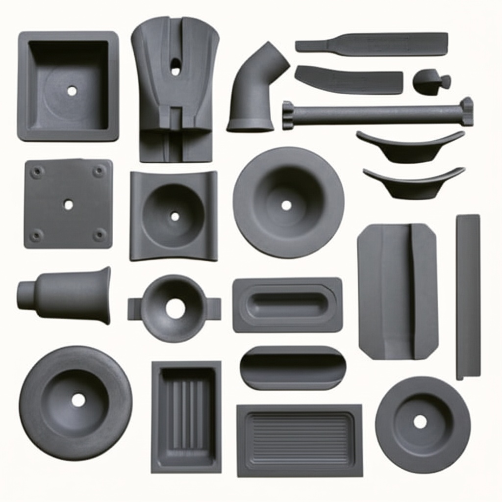
The demanding environment of aerospace propulsion systems, characterized by extreme temperatures, high pressures, and corrosive gases, necessitates materials that can withstand these challenges without faltering. Silicon carbide and its composites are increasingly specified for a range of critical components. These applications leverage SiC’s inherent properties to enhance performance, extend service life, and reduce system weight.
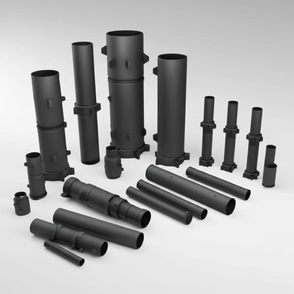
- Rocket Engine Nozzles and Throats: SiC’s ability to withstand ultra-high temperatures (often exceeding 2000°C) and resist erosion from hot, high-velocity exhaust gases makes it ideal for rocket nozzle throats, exit cones, and diverters. Custom SiC nozzles maintain their structural integrity and dimensional stability, ensuring consistent thrust and engine performance.
- Turbine Engine Components: In gas turbine engines, SiC is used for components such as combustor liners, turbine vanes, blades, and shrouds. Its high strength-to-weight ratio at elevated temperatures allows for hotter combustion, leading to improved fuel efficiency and reduced emissions. Silicon carbide matrix composites (CMCs), particularly C/SiC (carbon fiber reinforced silicon carbide), are gaining traction here.
- Hypersonic Vehicle Components: For hypersonic aircraft and missiles, leading edges, nose cones, and control surfaces experience extreme aerodynamic heating. SiC’s thermal shock resistance and high emissivity are crucial for these applications, preventing material degradation at Mach 5+ speeds.
- Thruster Components for Satellites and Spacecraft: Ion thrusters and Hall thrusters used for satellite station-keeping and deep space missions benefit from SiC’s wear resistance and electrical properties for components like discharge channels and grids.
- Heat Exchangers and Recuperators: Aerospace systems requiring compact, lightweight, and highly efficient heat exchangers, especially in regenerative engine cycles, utilize SiC for its excellent thermal conductivity and resistance to fouling and corrosion.
- Mirrors and Optical Systems: While not directly propulsion, SiC’s stability and polishability make it suitable for mirrors in aerospace optical systems that might be integrated near propulsion units, requiring stability across temperature gradients.
- Bearings and Seals: In high-speed rotating machinery within propulsion systems, SiC bearings and seals offer low friction, high wear resistance, and can operate with minimal lubrication under extreme temperatures. You can see some examples of how these advanced materials are employed in our project showcases.
The adoption of SiC in these areas is driven by the constant push for higher performance metrics: greater thrust-to-weight ratios, longer operational lifespans, improved fuel economy, and the ability to operate in increasingly hostile environments.
Why Choose Custom Silicon Carbide for Aerospace Propulsion? The Performance Edge
While standard SiC components offer significant advantages, the unique and often extreme demands of aerospace propulsion necessitate custom silicon carbide solutions. Off-the-shelf parts may not fully optimize performance or fit the specific geometric and operational constraints of advanced propulsion designs. Customization unlocks the full potential of SiC, providing a distinct performance edge.
Key benefits of opting for custom SiC in aerospace propulsion include:
- Optimized Geometric Design: Aerospace components often feature complex geometries to maximize aerodynamic efficiency, manage thermal stresses, or integrate with other parts. Custom fabrication allows for the creation of SiC parts that precisely match these intricate designs, something not achievable with stock components. This includes features like internal cooling channels or specific mounting interfaces.
- Tailored Material Properties: Customization can extend to the material composition itself. Specific grades of SiC (e.g., reaction-bonded, sintered, nitride-bonded, or even SiC composites) can be selected or slightly modified to enhance particular properties like thermal shock resistance, fracture toughness, or electrical conductivity, depending on the exact application requirements.
- Enhanced Thermal Management: SiC’s high thermal conductivity is a major asset. Custom designs can incorporate features that further optimize heat dissipation or thermal barrier functions, crucial for components exposed to combustion gases or aerodynamic heating.
- Weight Reduction: SiC is inherently lighter than many superalloys used in high-temperature applications. Custom design ensures that SiC components are fabricated with minimal material usage without compromising structural integrity, contributing directly to lower overall system weight and improved thrust-to-weight ratios.
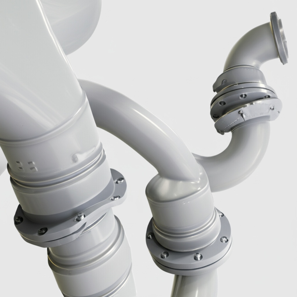
- Improved System Integration: Custom SiC parts are designed for seamless integration with mating components made from other materials. This includes precise tolerances for interfaces, considerations for differential thermal expansion, and the incorporation of joining features.
- Increased Reliability and Lifespan: By tailoring the SiC component to the specific stresses and environmental conditions it will face, its durability and operational lifespan can be significantly enhanced. This reduces maintenance cycles and improves the overall reliability of the propulsion system.
- Application-Specific Performance: Whether it’s maximizing erosion resistance in a rocket nozzle or ensuring dielectric properties in a thruster component, custom SiC allows engineers to prioritize the performance characteristics most critical for their application. Our team excels in providing customizing support to meet such precise needs.
In essence, custom silicon carbide empowers aerospace engineers to push the boundaries of propulsion technology, moving beyond the limitations of standard materials and designs to achieve unprecedented levels of performance and efficiency.
Recommended SiC Grades and Compositions for Aerospace Excellence
The selection of the appropriate silicon carbide grade is paramount for ensuring optimal performance and longevity in demanding aerospace applications. Different manufacturing processes yield SiC materials with varying microstructures and, consequently, distinct thermomechanical properties. Key SiC grades relevant to aerospace propulsion include:
| SiC Grade | Key Characteristics | Typical Aerospace Applications |
|---|---|---|
| Sintered Silicon Carbide (SSiC) | High density (typically >98%), excellent strength and hardness at high temperatures, superior chemical inertness, good thermal shock resistance. Produced by sintering fine SiC powder at high temperatures (2000-2200°C), sometimes with non-oxide sintering aids. | Turbine components (vanes, blades), heat exchanger tubes, bearings, seals, rocket motor components requiring high purity and temperature capability. |
| Reaction-Bonded Silicon Carbide (RBSiC or SiSiC) | Contains a percentage of free silicon (typically 8-15%), good thermal conductivity, excellent wear and abrasion resistance, relatively easier to produce complex shapes. Manufactured by infiltrating a porous carbon-SiC preform with molten silicon. | Rocket nozzles, combustor liners, wear-resistant components, structural supports where extreme high-temperature strength is secondary to thermal conductivity and manufacturability of complex shapes. Limited by the melting point of silicon (~1414°C). |
| Nitride-Bonded Silicon Carbide (NBSiC) | SiC grains bonded by a silicon nitride (Si3N4) phase. Offers good thermal shock resistance, high hot strength, and resistance to molten metal corrosion (less relevant for propulsion but indicates robustness). | Specialized components requiring excellent thermal cycling resistance, though less common than SSiC or RBSiC in primary propulsion structures. |
| Chemical Vapor Deposited SiC (CVD-SiC) | Ultra-high purity SiC, typically used as a coating or for producing thin, dense components. Excellent oxidation and corrosion resistance. | Protective coatings on graphite or C/C composites, thin optical components, semiconductor applications (though relevant for aerospace electronics). |
| Carbon Fiber-Reinforced Silicon Carbide (C/SiC Composites – a type of CMC) | SiC matrix reinforced with carbon fibers. Offers significantly improved fracture toughness (“graceful failure”) compared to monolithic SiC, lightweight, excellent high-temperature strength and thermal shock resistance. | Hot-structure components in advanced turbine engines (e.g., shrouds, flaps, seals), rocket nozzles, leading edges for hypersonic vehicles. More expensive and complex to manufacture. |
| Silicon Carbide Fiber-Reinforced Silicon Carbide (SiC/SiC Composites – a type of CMC) | SiC matrix reinforced with SiC fibers. Provides the highest temperature capability among CMCs (potentially >1650°C), excellent oxidation resistance, and good toughness. | Most demanding applications in next-generation jet engines, hypersonic vehicles, and reusable launch systems. Represents the cutting edge of SiC technology. |
Choosing the right grade involves a careful analysis of the operating temperature, mechanical stresses, thermal cycling conditions, chemical environment, desired lifespan, and, critically, cost considerations. Consultation with experienced technical ceramics specialists is crucial for making an informed decision that aligns with the specific aerospace propulsion requirements.
Design Considerations for Custom SiC Aerospace Propulsion Products
Designing components with silicon carbide for aerospace propulsion requires a different mindset than when working with metals or polymers. SiC’s inherent brittleness, while offset by its incredible hardness and thermal properties, means that careful attention must be paid to design details to ensure manufacturability, structural integrity, and optimal performance.
Key design considerations include:
- Managing Brittleness:
- Avoid sharp internal corners and stress concentrators; use generous radii instead.
- Design for compressive loads where possible, as ceramics are much stronger in compression than in tension.
- Consider prestressing techniques or reinforcement (as in CMCs) for components subjected to high tensile or flexural stresses.
- Incorporate features that prevent point loads; distribute loads over larger areas.
- Thermal Management:
- Analyze thermal gradients and thermal shock potential. SiC has good thermal shock resistance, but extreme, rapid temperature changes can still induce fracture.
- Design for uniform heating and cooling where possible.
- Consider the coefficient of thermal expansion (CTE) mismatches when SiC is joined to other materials. Design joints to accommodate these differences (e.g., using compliant interlayers or mechanical attachments).
- Manufacturability and Geometry:
- Forming Processes: Understand the limitations of the chosen SiC grade’s forming process (e.g., pressing, slip casting, extrusion, injection molding for green bodies, or direct machining for some grades). Complex internal cavities might be challenging or expensive.
- Wall Thickness: Maintain uniform wall thicknesses where possible to aid in sintering and reduce internal stresses. Minimum achievable wall thickness depends on the manufacturing process and part size.
- Draft Angles: For pressed or molded parts, incorporate draft angles to facilitate demolding.
- Machining Allowances: If post-sintering machining (grinding) is required for tight tolerances, ensure sufficient material allowance is included in the green or sintered part design.
- Joining and Assembly:
- Design for mechanical fastening where feasible, using compliant layers to distribute clamping forces.
- Consider brazing or specialized ceramic joining techniques if a monolithic assembly is required, accounting for CTE differences and service temperature.
- Factor in accessibility for assembly and disassembly if maintenance is anticipated.
- Surface Finish and Tolerances:
- Specify surface finish requirements based on functional needs (e.g., aerodynamic smoothness, seal interface). Very fine finishes require extensive grinding.
- Define critical tolerances and be aware that extremely tight tolerances significantly increase manufacturing costs.
- Component Integration:
- Ensure the SiC component design fits harmoniously within the larger propulsion system.
- Consider interfaces with sensors, actuators, or fuel lines.
- Cost Implications:
- Complexity drives cost. Simplify designs where possible without compromising function.
- The choice of SiC grade and the need for extensive post-processing also impact cost.
Collaborating closely with your SiC supplier early in the design phase is crucial. Experienced suppliers can provide invaluable insights into design for manufacturability (DFM) for ceramics, helping to optimize the design for performance, reliability, and cost-effectiveness. This collaborative approach can prevent costly redesigns and ensure the final SiC component meets all aerospace propulsion demands.
Precision Perfected: Tolerance, Surface Finish & Dimensional Accuracy in Aerospace SiC
In the high-stakes world of aerospace propulsion, precision is not just a goal; it’s a fundamental requirement. Silicon carbide components, often operating in critical assemblies, demand exacting tolerances, specific surface finishes, and high dimensional accuracy to ensure optimal performance, safety, and system efficiency. Achieving this level of precision with a hard, brittle material like SiC requires specialized manufacturing expertise and advanced machining techniques.
Achievable Tolerances:
The achievable dimensional tolerances for SiC components depend on several factors:
- SiC Grade: Different grades (RBSiC, SSiC) have different shrinkage rates and behaviors during sintering, influencing as-sintered tolerances.
- Manufacturing Process: Near-net-shape forming techniques (e.g., injection molding, slip casting) can produce parts with good initial tolerances. However, for the tightest tolerances, post-sintering diamond grinding is almost always necessary.
- Part Size and Complexity: Larger and more complex parts inherently present greater challenges in maintaining tight tolerances throughout the component.
- Machining Capabilities: The sophistication of the grinding equipment and the skill of the machinists are critical.
Typical achievable tolerances for ground SiC components are often in the range of:
- Dimensional Tolerances: Down to ±0.005 mm (±0.0002 inches) or even tighter for critical features, though this significantly increases cost. More common are tolerances of ±0.01 mm to ±0.05 mm.
- Parallelism, Flatness, Roundness: Can be controlled to within a few micrometers (µm) for precision surfaces.
Surface Finish Options:
Surface finish is critical for various reasons in aerospace propulsion, including minimizing friction, ensuring proper sealing, and optimizing aerodynamic or fluid dynamic performance.
- As-Sintered Finish: The surface finish of a part directly after sintering is typically rougher and depends on the green forming process and grain size of the SiC. It might be suitable for some internal or non-critical surfaces. Ra values can range from 1 µm to 10 µm or more.
- Ground Finish: Diamond grinding is the most common method for achieving improved surface finishes and tight tolerances. Ground surfaces can typically achieve Ra values from 0.2 µm to 0.8 µm.
- Lapped/Polished Finish: For applications requiring exceptionally smooth surfaces (e.g., high-performance seals, mirror substrates, some bearing raceways), lapping and polishing processes can be employed. These can achieve Ra values below 0.05 µm, sometimes down to angstrom levels for optical applications.
Ensuring Dimensional Accuracy:
Dimensional accuracy is maintained through a combination of:
- Process Control: Strict control over raw material quality, forming processes, and sintering cycles to minimize variability.
- Advanced Machining: Utilizing precision CNC diamond grinding machines, specialized tooling, and optimized grinding parameters.
- Metrology: Employing sophisticated measurement equipment, such as Coordinate Measuring Machines (CMMs), optical profilometers, and laser interferometers, to verify dimensions and surface characteristics.
- Quality Management Systems: Adherence to rigorous quality standards (e.g., AS9100 for aerospace) ensures that processes are repeatable and components consistently meet specifications.
Procurement managers and engineers should clearly define the required tolerances and surface finishes on their drawings and specifications, understanding that tighter requirements invariably lead to increased manufacturing time and cost. A collaborative discussion with the SiC supplier can help determine the optimal balance between precision, performance, and cost for specific aerospace propulsion components.
Post-Processing Needs: Optimizing SiC Components for Aerospace Demands
While the inherent properties of silicon carbide make it a standout material for aerospace propulsion, post-processing steps are often crucial to further enhance its performance, ensure dimensional accuracy, and meet the stringent requirements of specific applications. These secondary operations transform a sintered or near-net-shape SiC part into a finished component ready for assembly.
Common post-processing needs for SiC aerospace components include:
- Diamond Grinding: This is the most prevalent post-processing step. Due to SiC’s extreme hardness (second only to diamond and boron carbide), conventional machining tools are ineffective. Diamond-impregnated grinding wheels are used to:
- Achieve tight dimensional tolerances.
- Create precise geometric features (holes, slots, chamfers).
- Produce desired surface finishes.
- Remove any minor distortions or excess material from the sintering process.
- Lapping and Polishing: For applications demanding exceptionally smooth and flat surfaces, such as seals, bearings, or optical components, lapping and polishing are employed after grinding. These processes use progressively finer abrasive slurries (often diamond-based) to achieve mirror-like finishes and sub-micron tolerances.
- Edge Honing/Chamfering: Sharp edges on brittle ceramic components can be points of stress concentration and are prone to chipping. Edge honing or chamfering creates small, controlled radii or bevels on edges to improve handling robustness and reduce the risk of fracture initiation.
- Cleaning: Thorough cleaning is essential to remove any contaminants, machining fluids, or particulate matter from the manufacturing and post-processing stages. This is critical for components used in sensitive aerospace systems, especially those involving propellants or optical paths. Specialized ultrasonic cleaning or chemical cleaning methods may be used.
- Coatings: Although SiC has excellent inherent oxidation and corrosion resistance, specialized coatings can be applied to further enhance these properties or to add new functionalities:
- Environmental Barrier Coatings (EBCs): For ultra-high temperature applications, particularly with SiC/SiC CMCs in turbine engines, EBCs protect against water vapor and other corrosive species in the combustion environment, extending component life.
- Anti-Oxidation Coatings: For certain grades or extreme conditions, coatings can provide additional protection against oxidation.
- Wear-Resistant Coatings: While SiC is very wear-resistant, specialized coatings like Diamond-Like Carbon (DLC) can be applied for specific tribological pairings.
- Joining/Brazing Preparations: If SiC components are to be joined to other SiC parts or metallic structures via brazing, specific surface preparations (e.g., metallization) might be required as a post-processing step to ensure a strong, reliable bond.
- Non-Destructive Testing (NDT): While technically an inspection step, NDT methods like X-ray inspection, ultrasonic testing, or fluorescent penetrant inspection (FPI) are often performed after critical post-processing operations to ensure the component is free from internal flaws, cracks, or surface defects that could compromise its integrity.
The extent and type of post-processing are dictated by the application’s specific requirements, the chosen SiC grade, and the initial forming method. Each step adds to the component’s cost and lead time, so it’s essential to specify only necessary operations. Collaborating with a knowledgeable SiC supplier who possesses comprehensive in-house post-processing capabilities can streamline the production process and ensure the final component meets all aerospace performance criteria.
Common Challenges in Aerospace SiC and How to Overcome Them with Expert Solutions
Despite its superior properties, the adoption and implementation of silicon carbide in aerospace propulsion are not without challenges. Understanding these potential hurdles and knowing how to address them is key to successfully leveraging SiC’s benefits. Most challenges stem from SiC’s inherent hardness and brittleness, as well as the complexities of its manufacturing processes.
Here are some common challenges and strategies to overcome them:
- Brittleness and Low Fracture Toughness:
- Challenge: Monolithic SiC is brittle, meaning it can fracture suddenly under impact or high tensile stress without significant plastic deformation. This is a primary concern for components subjected to vibrations, thermal shock, or potential foreign object damage (FOD).
- Solutions:
- Design Optimization: Employ ceramic-friendly design principles (e.g., generous radii, avoiding stress concentrators, designing for compression).
- Material Selection: Utilize tougher SiC grades or, for critical applications, opt for SiC-based Ceramic Matrix Composites (CMCs like C/SiC or SiC/SiC) which offer pseudo-ductility and much higher fracture toughness.
- Proof Testing: Implement rigorous proof testing of components to weed out parts with critical flaws.
- Protective Mountings/Housings: Design surrounding structures to protect SiC components from direct impact.
- Machining Complexity and Cost:
- Challenge: SiC’s extreme hardness makes it difficult and time-consuming to machine. Only diamond tooling can effectively cut or grind SiC, leading to higher machining costs and longer lead times compared to metals.
- Solutions:
- Near-Net-Shape Forming: Utilize manufacturing processes (e.g., slip casting, injection molding, 3D printing of green bodies) to produce parts as close to the final dimensions as possible, minimizing the amount of material to be removed by grinding.
- Advanced Grinding Techniques: Partner with suppliers who have expertise in CNC diamond grinding, ultrasonic-assisted machining, or laser machining for SiC.
- Design for Manufacturability (DFM): Simplify designs where possible and consult with SiC specialists early in the design phase to optimize for machining efficiency.
- Joining SiC to Other Materials:
- Challenge: Joining SiC to metals or other ceramics can be difficult due to differences in Coefficients of Thermal Expansion (CTE), leading to stress at the joint during thermal cycling.
- Solutions:
- Brazing: Use active braze alloys specifically designed for ceramic-to-metal joining. Design joints to accommodate stress (e.g., using compliant interlayers).
- Mechanical Fastening: Design robust mechanical attachments, often incorporating compliant gaskets or washers to distribute loads and absorb CTE mismatch.
- Diffusion Bonding: A high-temperature, high-pressure process that can create strong bonds, but is complex and part-specific.
- Graded Interlayers: In some advanced applications, interlayers with gradually changing CTEs can be used.
- Thermal Shock Susceptibility:
- Challenge: While SiC generally has good thermal shock resistance, very rapid and severe temperature changes can still induce cracking, especially in complex shapes or constrained parts.
- Solutions:
- Material Selection: Grades like RBSiC or certain SSiC formulations offer better thermal shock resistance. CMCs are significantly more resistant.
- Design Considerations: Design parts to minimize thermal gradients and allow for thermal expansion.
- Operational Controls: Where possible, manage heating and cooling rates in the application.
- Cost of Raw Materials and Processing:
- Challenge: High-purity SiC powders and the energy-intensive processes required for sintering and machining contribute to a higher component cost compared to many conventional materials.
- Solutions:
- Application-Specific Grade Selection: Don’t over-specify. Use the most cost-effective SiC grade that meets all performance requirements.
- Volume Production: Costs tend to decrease with higher production volumes.
- Strategic Sourcing: Work with experienced suppliers who have optimized their manufacturing processes and supply chains. Reviewing past successful implementations can provide insight into a supplier’s capability to deliver value.
- Quality Control and NDT:
- Challenge: Detecting small critical flaws in ceramic components requires specialized Non-Destructive Testing (NDT) techniques and expertise.
- Solutions:
- Advanc
- Advanc

About the Author: Sicarb Tech
We provide clear and reliable insights into silicon carbide materials, component manufacturing, application technologies, and global market trends. Our content reflects industry expertise, practical experience, and a commitment to helping readers understand the evolving SiC landscape.

Customizable SiC
You May Also Interest
-
![]()
SiC Academic Research Insights for Industry Use
SiC Academic Research Insights for Industry Use In the relentless pursuit of performance and efficiency across demanding industrial sectors, silicon carbide (SiC) has emerged as a cornerstone material. Its exceptional properties—ranging from unparalleled hardness and wear resistance to superior thermal conductivity and chemical inertness—make it indispensable for high-stakes applications. This blog post delves into the…
-
![]()
Precision SiC Rings for Reliable Mechanical Seals
Precision SiC Rings for Reliable Mechanical Seals In the demanding world of industrial applications, the reliability of every component is paramount. Mechanical seals play a critical role in preventing leakage, containing pressure, and excluding contaminants in rotating equipment. At the heart of these seals, the choice of material for seal faces is crucial for performance…
-
![]()
Key SiC Exporters in Asia for International Trade
Key SiC Exporters in Asia for International Trade In the rapidly evolving landscape of advanced materials, silicon carbide (SiC) stands out as a material of unparalleled performance. Its exceptional properties make it indispensable across a spectrum of demanding industrial applications. For businesses seeking reliable and high-quality silicon carbide products, understanding the key players and regions…